TMC5130A DATASHEET (Rev. 1.14 / 2017-MAY-15)
119
30.3 Thermal Characteristics
The following table shall give an idea on the thermal resistance of the package. The thermal
resistance for a four layer board will provide a good idea on a typical application. Actual thermal
characteristics will depend on the PCB layout, PCB type and PCB size. The thermal resistance will
benefit from thicker CU (inner) layers for spreading heat horizontally within the PCB. Also, air flow will
reduce thermal resistance.
A thermal resistance of 21K/W for a typical board means, that the package is capable of continuously
dissipating 4.7W at an ambient temperature of 25°C with the die temperature staying below 125°C.
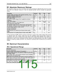
Parameter
Symbol Conditions
Typ
Unit
Typical power dissipation
PD
stealthChop or spreadCycle, 1A RMS in
3.0
W
two phase motor, sinewave, 40 or
20kHz chopper, 24V, internal supply,
85°C peak surface of package (motor
QSH4218-035-10-027)
Thermal resistance junction to
ambient on a multilayer board
RTMJA
Dual signal and two internal power
plane board (2s2p) as defined in
JEDEC EIA JESD51-5 and JESD51-7
(FR4, 35µm CU, 70mm x 133mm,
d=1.5mm)
21
K/W
Thermal resistance junction to
board
RTJB
RTJC
PCB temperature measured within
1mm distance to the package leads
8
3
K/W
K/W
Thermal resistance junction to
case
Junction temperature to heat slug of
package
Table 30.1 Thermal characteristics TQFP48-EP
The thermal resistance in an actual layout can be tested by checking for the heat up caused by the
standby power consumption of the chip. When no motor is attached, all power seen on the power
supply is dissipated within the chip.
Note
A spread-sheet for calculating TMC5130 power dissipation is available on www.trinamic.com.
www.trinamic.com

 TRINAMIC [ TRINAMIC MOTION CONTROL GMBH & CO. KG. ]