TK6591x
APPLICATION INFORMATION (CONT.)
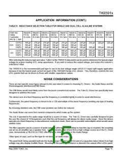
TABLE 5: INDUCTANCE SELECTION TABLE FOR SINGLE AND DUAL CELL ALKALINE SYSTEMS
PART NO.
f lamp
f converter
min.Vp L type
TK65910 TK65911 TK65912 TK65913 TK65914 TK65915 TK65916 TK65917 TK65918 TK65919
175 Hz 200 Hz 225 Hz 250 Hz 275 Hz 300 Hz 325 Hz 350 Hz 375 Hz 400 Hz
22.4 kHz 25.6 kHz 28.8 kHz 32.0 kHz 35.2 kHz 38.4 kHz 41.6 kHz 44.8 kHz 48.0 kHz 51.2 kHz
D31FU
0.9V D32FU
D52FU
330 µH
390 µH
560 µH
270 µH
390 µH
470 µH
270 µH
390 µH
470 µH
270 µH
330 µH
390 µH
270 µH
330 µH
390 µH
220 µH
330 µH
390 µH
220 µH
330 µH
330 µH
220 µH
---
330 µH
220 µH
---
330 µH
220 µH
---
330 µH
D31FU
1.8V D32FU 1000 µH
680 µH
680 µH
820 µH
680 µH
820 µH
680 µH
820 µH
680 µH
680 µH
820 µH
560 µH
680 µH
820 µH
560 µH
680 µH
820 µH
560 µH
680 µH
820 µH
560 µH
680 µH
680 µH
470 µH
560 µH
680 µH
D52FU 1200 µH 1200 µH 1000 µH 1000 µH
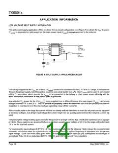
After selecting the inductor type and value, Table 4 of the TK6591X data sheet can be used to determine the typical output
voltage for a given loading of EL lamp capacitance. If you wish to reduce this output voltage, just reduce the inductor’s
inductance value.
The TK6591X is the recommended part type to use in the low voltage single cell (0.9 V input) split supply application
because it has the lowest peak current set point of the TK659XX family of EL drivers. This, therefore, restricts the size
of EL panels that can be driven to those with smaller capacitance values.
NOISE CONSIDERATIONS
There are two specific noise types relevant to the user when it comes to choosing EL Drivers: the Audio Noise and the
Electromagnetic Interference(EMI) Noise.
The EMI Noise would most likely come from the boost converter/coil section. The Toko EL Driver has specifically been
designed to address this issue.
The device runs at a fixed frequency and the frequency is controlled tightly in order to avoid interference.
Furthermore, the panel frequency is forced to be a 128 submultiple of the boost frequency avoiding any type of beating
frequencies.
By choosing shielded coils, the EMI noise problem can further be reduced.
The Audio Noise can come from several components which make up the system.
The coil, if operated in the audio range would be a source of noise. The Toko EL Driver was carefully designed to give
the user the choice of 10 frequencies such that the coil frequency will always be above audio range. Since the device
operates at a fixed frequency in discontinuous conduction mode, there are no possible submultiples which would cause
audible noise.
The filter capacitor can be a source of audio noise. Furthermore, depending on how this cap is mounted, the mounting
can act as an amplifier (as a speaker box). Certain ceramic caps driven from a high voltage source as in the EL Driver
case, demonstrate a PIEZOELECTRIC effect which is distinguishable in the Audio Range.
Other types of caps, such as film type do not denote an audio noise.
The panel itself, being operated well into the Audio Range (175 Hz to 400 Hz) and of a capacitive nature driven from high
voltage may also display Audible Noise. Mounting of this panel can enhance or diminish this natural effect of the panel.
May 2000 TOKO, Inc.
Page 15

 TOKO [ TOKO, INC ]