TK6591x
DESIGN CONSIDERATIONS
INDUCTOR VALUE SELECTION
Designing an EL Driver utilizing the TK6591x is a very simple task. The primary component affecting the behavior of the
converter is the inductor. Essentially, the entire design task primarily consists of selecting the proper inductor value and
type given the operating conditions of the EL Panel (e.g., lamp capacitance, frequency, output voltage, supply range).
The following tables and charts are intended to simplify the selection of the inductor.
Given the capacitance of the EL Lamp, and the peak output voltage requirements, the following table can be utilized to
select the value of the inductive component.
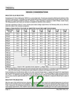
TABLE 4: PEAK OUTPUT VOLTAGE VS. INDUCTOR VALUE AND LAMP CAPACITANCE
INDUCTOR
VALUE
3.5 nF
LAMP
5.0 nF
LAMP
6.5 nF
LAMP
8.0 nF
LAMP
9.5 nF
LAMP
11.0 nF
LAMP
12.5 nF
LAMP
220 µH
270 µH
330 µH
390 µH
470 µH
560 µH
680 µH
820 µH
1000 µH
1200 µH
1500 µH
1800 µH
2200 µH
2700 µH
3300 µH
45 V
50 V
52 V
57 V
62 V
68 V
75 V
82 V
38 V
42 V
44 V
47 V
52 V
57 V
63 V
69 V
76 V
83 V
33 V
37 V
38 V
42 V
46 V
50 V
55 V
60 V
67 V
73 V
82 V
89 V
30 V
33 V
34 V
37 V
41 V
45 V
49 V
54 V
60 V
66 V
73 V
80 V
89 V
28 V
30 V
32 V
34 V
38 V
41 V
45 V
50 V
55 V
60 V
67 V
74 V
82 V
90 V
26 V
28 V
29 V
32 V
35 V
38 V
42 V
46 V
51 V
56 V
63 V
69 V
76 V
84 V
24 V
26 V
28 V
30 V
33 V
36 V
40 V
43 V
48 V
53 V
59 V
64 V
71 V
79 V
87 V
Close to 100 V operation check capacitor C1 voltage rating
Note: The voltages indicated in the table above may not be achievable under certain circumstances (i.e., low battery or higher drive frequencies).
Refer to the charts on page 12 to determine which output voltage/coil combination can be supported by the EL driver.
As an example as to how the above table is to be used, assume that we have a 1-square-inch panel (5 nF capacitance)
and we would like the peak-to-peak voltage across the lamp to be 140 V. The peak voltage on either terminal would be
70 V (140 V / 2). Referring to the table above, we can see that using a 820 µH coil the peak voltage developed across
a 5 nF Lamp would be approximately 69 V. In this particular example, the inductive component should have a value of
820 µH.
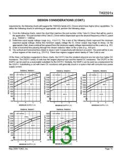
INDUCTOR TYPE SELECTION
After the value of the inductor has been selected, an appropriate coil type needs to be selected taking into account such
factors as DC resistance and current capability. The following charts can be utilized for selecting the proper family of Toko
Coils. Furthermore, the following charts will also indicate if the TK6591x is the appropriate driver given the frequency and
input supply requirements. If the TK6591x does not have sufficient drive capability given the input supply and frequency
Page 12
May 2000 TOKO, Inc.

 TOKO [ TOKO, INC ]