UCD90320
ZHCSFI3B –AUGUST 2016–REVISED MAY 2019
www.ti.com.cn
8.4.4 Fault Responses Configuration
In the previous sections, various fault and warn notification thresholds have been configured to monitor voltage,
current, temperature, and turn-ON time and turn-OFF time. When a fault threshold is reached, a fault event
occurs. The device performs the following three actions in response of a fault event.
•
•
•
Asserts the PMBus ALERT line
Logs the fault event into nonvolatile memory (data flash), set status register bit
Executes fault responses defined by users
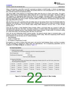
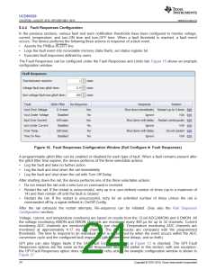
The Fault Responses can be configured under the Fault Responses and Limits tab. Figure 16 shows an example
configuration window.
Figure 16. Fault Responses Configuration Window (Rail Configure ► Fault Responses)
A programmable glitch filter can be enabled or disabled for each type of fault. When a fault remains present after
the glitch filter time expires, the device performs of the three selectable actions:
•
•
•
Log the fault and take no further action
Log the fault and shut down the rail immediately
Log the fault and shut down the rail with Turn Off Delay
After shutting down the rail, the device performs one of the three selectable actions:
•
•
Do not restart the rail until a new turn-on command is received
Restart the rail. If the restart is unsuccessful, retry up to a user-defined number of times (up to a maximum of
14) and then remain off until the fault is cleared
•
Restart the rail. If the restart is unsuccessful, retry for an unlimited number of times unless the rail is
commanded off by a signal defined in On/Off Config .
After the rail exhausts the restart attempts, Re-sequence can be initiated. (See also the Rail Sequence
Configuration section).
Voltage, current, and temperature monitoring are based on results from the 12-bit ADC(AMON) and 8 DMON. All
the voltage monitoring AMON and DMON channels are monitored every 400 µs for up to 32 channels. Current
monitoring ADC channels are monitored at 200 µs per channel. Temperature monitoring ADC channels are
monitored at approximately 4.17 ms per channel. The ADC results are compared with the programmed
thresholds. The time to respond to an individual event is determined by when the event occurs within the ADC
conversion cycle and the configured fault responses (glitch filters, time delays, and so forth).
GPI pins can also trigger faults if the GPI Fault Enable checkbox in Figure 12 is checked. The GPI Fault
Responses options are the same as the Fault Responses discussed earlier in this section, with one exception:
the GPI Fault Responses option does not support the retry action. An example configuration window is shown in
Figure 17.
24
Copyright © 2016–2019, Texas Instruments Incorporated

 TI [ TEXAS INSTRUMENTS ]