UCC28180
www.ti.com
SLUSBQ5A –NOVEMBER 2013–REVISED NOVEMBER 2013
APPLICATION INFORMATION
UCC28180 Operation
The UCC28180 is a switch-mode controller used in boost converters for power factor correction operating at a
fixed frequency in continuous conduction mode. The UCC28180 requires few external components to operate as
an active PFC pre-regulator. The operating switching frequency can be programmed from 18 kHz to 250 kHz
simply by connecting the FREQ pin to ground through a resistor.
The internal 5-V reference voltage provides for accurate output voltage regulation over the typical world-wide 85-
VAC to 265-VAC mains input range from zero to full output load. The usable system load ranges from 100 W to
few kW.
Regulation is accomplished in two loops. The inner current loop shapes the average input current to match the
sinusoidal input voltage under continuous inductor current conditions. Under light-load conditions, depending on
the boost inductor value, the inductor current may go discontinuous but still meet Class-A/D requirements of IEC
61000-3-2 despite the higher harmonics. The outer voltage loop regulates the PFC output voltage by generating
a voltage on VCOMP (dependent upon the line and load conditions) which determines the internal gain
parameters for maintaining a low-distortion, steady-state, input-current wave shape.
Bias Supply
The UCC28180 operates from an external bias supply. It is recommended that the device be powered from a
regulated auxiliary supply. (This device is not intended to be used from a bootstrap bias supply. A bootstrap bias
supply is fed from the input high voltage through a resistor with sufficient capacitance on VCC to hold up the
voltage on VCC until current can be supplied from a bias winding on the boost inductor. For that reason, the
minimal hysteresis on VCC would require an unreasonable value of hold-up capacitance.)
During normal operation, when the output is regulated, current drawn by the device includes the nominal run
current plus the current supplied to the gate of the external boost switch. Decoupling of the bias supply must take
switching current into account in order to keep ripple voltage on VCC to a minimum. A ceramic capacitor of 0.1-
µF minimum value from VCC to GND with short, wide traces is recommended.
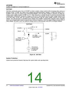
VCC
VCC(ON) 11.5V
VCC(
9.5V
OFF)
ICC
ICC(ON)
ICC(stby) < 2.95 mA
ICC(prestart) < 75 µA
Controller
State
Soft-
Start
UVLO
OFF
Run
Run
UVLO
OFF
Soft-Start
Fault/standby
OFF
PWM
State
Ramp
Regulated
Ramp Regulated
Figure 23. Device Supply States
The device's bias operates in several states. During startup, VCC Under-Voltage LockOut (UVLO) sets the
minimum operational DC input voltage of the controller. There are two UVLO thresholds. When the UVLO turn-on
threshold is exceeded, the PFC controller turns ON. If the VCC voltage falls below the UVLO turn-off threshold,
the PFC controller turns off. During UVLO, current drawn by the device is minimal. After the device turns on, Soft
Start (SS) is initiated and the boost inductor current is ramped up in a controlled manner to reduce the stress on
the external components and avoids output voltage overshoot. During soft start and after the output is in
regulation, the device draws its normal run current. If any of several fault conditions are encountered or if the
device is put in standby with an external signal, the device draws a reduced standby current.
Copyright © 2013, Texas Instruments Incorporated
Submit Documentation Feedback
13
Product Folder Links :UCC28180

 TI [ TEXAS INSTRUMENTS ]