UC2625-EP
www.ti.com .................................................................................................................................................................................................. SLUS802–MARCH 2008
+15V
VMOTOR
+5V TO HALL
SENSORS
VREF
+
3kW
100nF
100nF
100mF
+
2N3904
10W
20mF
20mF
10kW
10kW
3kW
ROSC
33kW
2
19
11
QUAD
DIR
2N3906
IRF9350
22
6
3kW
16
17
18
14
13
TO
MOTOR
1k
TO OTHER
CHANNELS
1
28
27
25
UC3625
4kW
REQUIRED
FOR BRAKE
AND FAST
REVERSE
100nF
TO OTHER
CHANNELS
10W
IRF532
2200pF
COSC
12
20
15
10kW
BRAKE
21
26
3
24
23
8
9
10
4
5
7
100nF
5nF
3nF
CT
68kW
RT
REQUIRED
FOR
240W
FROM
HALL
SENSORS
100nF
AVERAGE
CURRENT
SENSING
0.02
W
2nF
5nF
240W
51kW
2nF
2nF
RS
0.02
W
RD
VREF
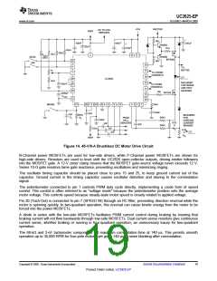
Figure 14. 45-V/8-A Brushless DC Motor Drive Circuit
N-Channel power MOSFETs are used for low-side drivers, while P-Channel power MOSFETs are shown for
high-side drivers. Resistors are used to level shift the UC2625 open-collector outputs, driving emitter followers
into the MOSFET gate. A 12-V zener clamp insures that the MOSFET gate-source voltage never exceeds 12 V.
Series 10-Ω gate resistors tame gate reactance, preventing oscillations and minimizing ringing.
The oscillator timing capacitor should be placed close to pins 15 and 25, to keep ground current out of the
capacitor. Ground current in the timing capacitor causes oscillator distortion and slaving to the commutation
signal.
The potentiometer connected to pin 1 controls PWM duty cycle directly, implementing a crude form of speed
control. This control is often referred to as "voltage mode" because the potentiometer position sets the average
motor voltage. This controls speed because steady-state motor speed is closely related to applied voltage.
Pin 20 (Tach-Out) is connected to pin 7 (SPEED IN) through an RC filter, preventing direction reversal while the
motor is spinning quickly. In two-quadrant operation, this reversal can cause kinetic energy from the motor to be
forced into the power MOSFETs.
A diode in series with the low-side MOSFETs facilitates PWM current control during braking by insuring that
braking current will not flow backwards through low-side MOSFETs. Dual current-sense resistors give continuous
current sense, whether braking or running in four-quadrant operation, an unnecessary luxury for two-quadrant
operation.
The 68-kΩ and 3-nF tachometer components set maximum commutation time at 140 µs. This permits smooth
operation up to 35,000 RPM for four-pole motors, yet gives 140 µs of noise blanking after commutation.
Copyright © 2008, Texas Instruments Incorporated
Submit Documentation Feedback
19
Product Folder Link(s) :UC2625-EP

 TI [ TEXAS INSTRUMENTS ]