UC2625-EP
SLUS802–MARCH 2008 .................................................................................................................................................................................................. www.ti.com
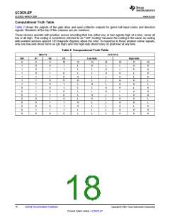
Computational Truth Table
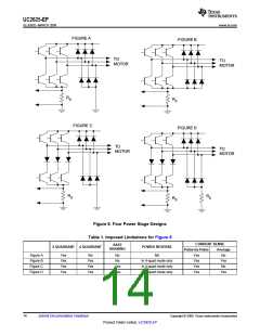
Table 2 shows the outputs of the gate drive and open collector outputs for given hall input codes and direction
signals. Numbers at the top of the columns are pin numbers.
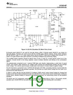
These devices operate with position sensor encoding that has either one or two signals high at a time, never all
low or all high. This coding is sometimes referred to as "120° Coding" because the coding is the same as coding
with position sensors spaced 120 magnetic degrees about the rotor. In response to these position sense signals,
only one low-side driver turns on (go high) and one high-side driver turns on (pull low) at any time.
Table 2. Computational Truth Table
INPUTS
OUTPUTS
DIR
6
H1
8
0
0
0
1
1
1
1
1
1
0
0
0
1
0
H2
9
0
1
1
1
0
0
0
0
1
1
1
0
1
0
H3
10
1
Low-Side
High-Side
12
L
13
H
L
14
L
16
L
17
H
H
L
18
H
H
H
H
L
1
1
1
L
H
H
L
L
1
0
L
L
H
H
H
H
H
L
1
0
H
H
L
L
L
1
0
L
L
H
H
L
1
1
H
L
L
L
0
1
L
H
H
L
H
H
H
L
0
0
L
L
H
H
H
H
L
0
0
L
H
H
L
L
0
0
L
L
H
H
H
H
H
0
1
H
H
L
L
L
0
1
L
L
H
H
H
X
X
1
L
L
H
H
0
L
L
L
18
Submit Documentation Feedback
Copyright © 2008, Texas Instruments Incorporated
Product Folder Link(s) :UC2625-EP

 TI [ TEXAS INSTRUMENTS ]