TPS65910, TPS65910A, TPS65910A3, TPS659101, TPS659102, TPS659103
TPS659104, TPS659105, TPS659106, TPS659107, TPS659108, TPS659109
SWCS046N –MARCH 2010–REVISED APRIL 2012
www.ti.com
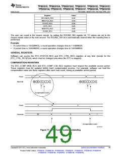
This drift can be balanced to compensate for any inaccuracy of the 32-kHz oscillator. Software must calibrate the
oscillator frequency, calculate the drift compensation versus one time hour period; and then load the
compensation registers with the drift compensation value. Indeed, if the AUTO_COMP_EN bit in the
RTC_CTRL_REG is enabled, the value of COMP_REG (in twos-complement) is added to the RTC 32-kHz
counter at each hour and one second. When COMP_REG is added to the RTC 32-kHz counter, the duration of
the current second becomes (32768 - COMP_REG)/32768s; so, the RTC can be compensated with a 1/32768
s/hour time unit accuracy.
NOTE
The compensation is considered once written into the registers.
BACKUP BATTERY MANAGEMENT
The device includes a back-up battery switch connecting the VRTC regulator input to a main battery (VCC7) or to
a back-up battery (VBACKUP), depending on the batteries voltage value.
The VRTC supply can then be maintained during a BACKUP state as far as the input voltage is high enough
(>VBNPR threshold). Below the VBNPR voltage threshold the digital core of the device is set under reset by
internal signal POR (PowerOnReset).
The back-up domain functions which are always supplied from VRTC comprehend:
•
•
The internal 32-kHz oscillator
Backup registers
The back-up battery can be charged from the main battery through an embedded charger. The back-up battery
charge voltage and enable is controlled through BBCH_REG register programming. This register content is
maintained during the device Backup state.
Hence enabled the back-up battery charge is maintained as far as the main battery voltage is higher than the
VMBLO threshold and the back-up battery voltage.
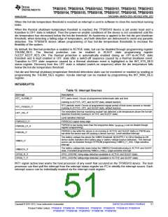
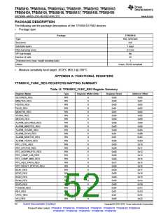
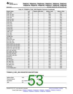
BACKUP REGISTERS
As part of the RTC the device contains five 8-bit registers which can be used for storage by the application
firmware when the external host is powered down. These registers retain their content as long as the VRTC is
active.
I2C INTERFACE
A general-purpose serial control interface (CTL-I2C) allows read and write access to the configuration registers of
all resources of the system.
A second serial control interface (SR-I2C) is dedicated to SmartReflex applications such as DVFS or AVS.
Both control interfaces are compliant with HS-I2C specification.
These interfaces support the standard slave mode (100 Kbps), Fast mode (400 Kbps), and high-speed mode
(3.4 Mbps). The general-purpose I2C module using one slave hard-coded addresse (ID1 = 2Dh). The
SmartReflex I2C module uses one slave hard-coded address (ID0 = 12h). The master mode is not supported.
Addressing: Seven-bit mode addressing device
They do not support the following features:
•
•
10-bit addressing
General call
THERMAL MONITORING AND SHUTDOWN
A thermal protection module monitors the junction temperature of the device versus two thesholds:
•
•
Hot-die temperature threshold
Thermal shutdown temperature theshold
50
Submit Documentation Feedback
Copyright © 2010–2012, Texas Instruments Incorporated
Product Folder Link(s): TPS65910 TPS65910A TPS65910A3 TPS659101 TPS659102 TPS659103 TPS659104
TPS659105 TPS659106 TPS659107 TPS659108 TPS659109

 TI [ TEXAS INSTRUMENTS ]