TPS65910, TPS65910A, TPS65910A3, TPS659101, TPS659102, TPS659103
TPS659104, TPS659105, TPS659106, TPS659107, TPS659108, TPS659109
www.ti.com
SWCS046N –MARCH 2010–REVISED APRIL 2012
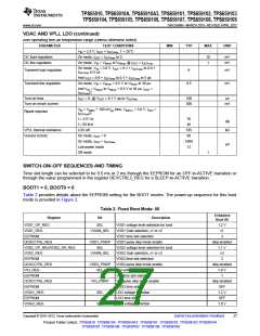
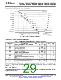
Figure 2 shows the 00 Boot mode timing characteristics.
tdSOFF2
PWRHOLD
tdSON1
1.8 V
1.8 V
VIO/VFBIO
VAUX1
tdSON2
VDD2/VFB2
VDD1/VFB1
VPLL
3.3 V
tdSON3
1.2 V
tdSON4
1.8 V
tdSON5
VDAC
1.8 V
1.8 V
VAUX2
tdSON6
VMMC
3.3 V
tdSON7
tdSOFF1
CLK32KOUT
NRESPWRON
tdSON8
tdSONT: Switch-on sequence
Switch-off sequence
SWCS046-018
Figure 2. Boot Mode: BOOT1 = 0, BOOT0 = 0
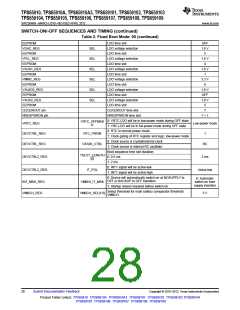
Table 3 lists the 00 Boot mode timing characteristics.
Table 3. Boot Mode: BOOT1 = 0, BOOT0 = 0 Timing Characteristics
PARAMETER
tdSON1
TEST CONDITIONS
PWRHOLD rising edge to VIO, VAUX1 enable delay
VIO to VDD2 enable delay
MIN
TYP
MAX
UNIT
µs
66 × tCK32k = 2060
64 × tCK32k = 2000
64 × tCK32k = 2000
64 × tCK32k = 2000
64 × tCK32k = 2000
64 × tCK32k = 2000
64 × tCK32k = 2000
64 × tCK32k = 2000
16
tdSON2
µs
tdSON3
VDD2 to VDD1 enable delay
µs
tdSON4
VDD1 to VPLL enable delay
µs
tdSON5
VPLL to VDAC,VAUX2 enable delay
VDAC to VMMC enable delay
µs
tdSON6
µs
VMMC to CLK32KOUT rising edge delay
CLK32KOUT to NRESPWRON rising edge delay
Total switch-on delay
µs
tdSON8
tdSONT
µs
ms
PWRHOLD falling edge to NRESPWRON falling edge
delay
tdSOFF1
tdSOFF1B
tdSOFF2
2 × tCK32k = 62.5
3 × tCK32k = 92
5 × tCK32k = 154
µs
µs
µs
NRESPWRON falling edge to CLK32KOUT low delay
PWRHOLD falling edge to supplies and reference
disable delay
Registers default setting: CK32K_CTRL = 1 (32-kHz RC oscillator is used), RTC_PWDN = 1 (RTC domain off),
IT_POL = 0 (INt2 interrupt flag active low), VMBHI_IT_MSK = 0 (automatic switch-on on Battery plug),
VMBCH_SEL = 11.
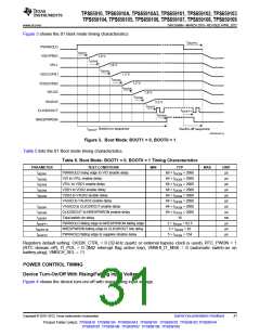
BOOT1 = 0, BOOT0 = 1
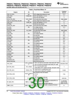
Table 4 provides details about the EEPROM setting for the BOOT modes. The power-up sequence for this boot
mode is provided in Figure 3.
Copyright © 2010–2012, Texas Instruments Incorporated
Submit Documentation Feedback
29
Product Folder Link(s): TPS65910 TPS65910A TPS65910A3 TPS659101 TPS659102 TPS659103 TPS659104
TPS659105 TPS659106 TPS659107 TPS659108 TPS659109

 TI [ TEXAS INSTRUMENTS ]