TPS61196
SLVSBG1C –OCTOBER 2012–REVISED FEBRUARY 2013
www.ti.com
Enable and Under Voltage Lockout
The TPS61196 is enabled with the soft startup when the EN pin voltage is higher than 1.8V. A voltage of less
than 1.0V disables the TPS61196.
An under voltage lockout protection feature is provided. When the voltage at the VIN pin is less than 6.5V, the
TPS61196 is powered off. The TPS61196 resumes the operation once the voltage at the VIN pin recovers above
the hysteresis (VVIN_HYS) more than the UVLO threshold of input falling voltage. If a higher under voltage lockout
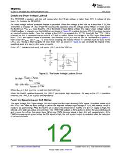
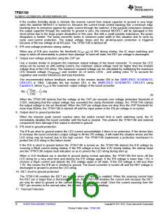
(UVLO) voltage is required, use the UVLO pin as shown in Figure 22 to adjust the input UVLO threshold by using
an external resistor divider. Once the voltage at the UVLO pin exceeds the 1.229V threshold, the TPS61196 is
powered on and a hysteresis current source of 3.9µA is added. When the voltage at the UVLO pin drops lower
than 1.229V, the current source is removed. The resistors of R1, R2 and R5 can be calculated by Equation 2
from required VSTART and VSTOP. To avoid noise coupling, the resistor divider R1 and R2 must be close to the
UVLO pin. Placing a filter capacitor of more than 10nF as shown in Figure 22 can eliminate the impact of the
switching ripple and improve the noise immunity.
If the UVLO function is not used, pull up the UVLO pin to the VDD pin.
VIN
R5
IHYS
R1
C4
UVLO
Enable
R2
UVLO
Comparator
1.229V
Figure 22. The Under Voltage Lockout Circuit
VSTART - VSTOP
R1+ R5 =
IHYS
1.229V
R2 = (R1+ R5)´
VSTART -1.229V
(2)
Where IHYS is 3.9uA sourcing current from the UVLO pin.
When the UVLO condition happens, the FAULT pin outputs high impedance. As long as the UVLO condition
removes, the FAULT pin outputs low impedance.
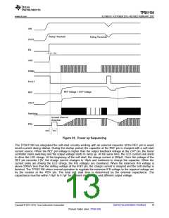
Power Up Sequencing and Soft Startup
The input voltage, UVLO pin voltage, EN input signal and the input dimming PWM signal control the power up of
the TPS61196. After the input voltage is above the required minimal input voltage of 7.5V, the internal circuit is
ready to be powered up. After the UVLO pin is above the threshold of 1.229V and the EN signal is high, the
internal LDO and logic circuit are activated. The TPS61196 outputs a 20ms pulse to detect the unused channels
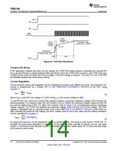
and remove them from the control loop. When any PWM dimming signal is high, the soft startup begins. If the
PWM dimming signals come before the EN signal is high, the soft startup begins immediately after the detection
of unused channels.
12
Submit Documentation Feedback
Copyright © 2012–2013, Texas Instruments Incorporated
Product Folder Links :TPS61196

 TI [ TEXAS INSTRUMENTS ]