TPS562212
ZHCSNA3 –OCTOBER 2021
www.ti.com.cn
VEN_FALL
VSATART
- VSTOP
VEN_RISE
VEN_FALL
VEN_RISE
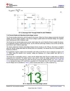
R1 =
≈
’
Ip 1-
+ I
h
∆
÷
÷
◊
∆
«
(3)
(4)
(5)
R1 ∂ VEN_FALL
R2 =
VSTOP - VEN_FALL + R ∂ I +I
1
p
h
R2 ∂ V +R1R2 I +I
(
)
IN
p
h
VEN
=
R1+R2
where
• Ip = 1.2 µA
• Ih = 3.1 µA
• VEN_FALL = 1.01 V
• VEN_RISE = 1.15 V
• VSTART = Expected input voltage enabling the device
• VSTOP = Expected input voltage disabling the device
7.3.7 Overcurrent Limit and Undervoltage Protection
The device is protected from overcurrent conditions by cycle-by-cycle current limiting on both the peak and
valley of the inductor current.
During the on time of the high-side MOSFET switch, the inductor current flows through the high-side MOSFET
and increases at a linear rate determined by the following:
• VIN
• VOUT
• On time
• Output inductor value
The high-side switch current is sensed when the high-side MOSFET is turned on after a set of blanking time and
then compared with the high-side MOSFET current limit threshold in every switching cycle. If the cross-limit
event is detected after the minimum on time, the high-side MOSFET is turned off immediately. The high-side
MOSFET current is limited by a clamped maximum peak current threshold, IHS_LIMIT, which is constant.
The current going through low-side MOSFET is also sensed and monitored. When the low-side MOSFET is
turned on, the inductor current begins ramping down. The low-side MOSFET is not turned off at the end of a
switching cycle if its current is above the low-side current limit, ILS_LIMIT. The low-side MOSFET is kept on for the
next cycle so that inductor current keeps ramping down until the inductor current ramps below the low-side
current limit, ILS_LIMIT, and the subsequent switching cycle comes, the low-side MOSFET is turned off, and the
high-side MOSFET is turned on after a dead time.
There are some important considerations for this type of overcurrent protection. The load current is higher than
the overcurrent threshold by one-half of the peak-to-peak inductor ripple current. Also, when the current is being
limited, the output voltage tends to fall as the demanded load current can be higher than the current available
from the converter. When the VFB voltage falls below the UVP threshold voltage, the UVP comparator detects it.
The device shuts down after the UVP delay time (typically 108 μs) and re-starts after the hiccup time (six times
of soft start time). The hiccup behavior helps reduce the device power dissipation under severe overcurrent
conditions.
When the overcurrent condition is removed, the output voltage returns to the regulated value.
Copyright © 2021 Texas Instruments Incorporated
14
Submit Document Feedback
Product Folder Links: TPS562212

 TI [ TEXAS INSTRUMENTS ]