TPS562212
ZHCSNA3 –OCTOBER 2021
www.ti.com.cn
VOUT(V)
1.8
R3_MIN(kW) =
- 0.4
(2)
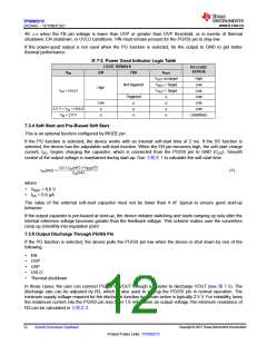
VIN
VIN
BOOT
TPS562212
C2
C1
L
VOUT
SW
PG/SS
FB
MODE
R1
R2
R3
EN
EN
C3
GND
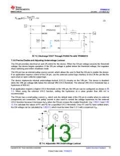
图7-2. Discharge VOUT Through PG/SS Pin with TPS562212
7.3.6 Precise Enable and Adjusting Undervoltage Lockout
The EN pin provides electrical on and off control for the device. When the EN pin voltage exceeds the threshold
voltage, the device begins operation. If the EN pin voltage is pulled below the threshold voltage, the regulator
stops switching and enters shutdown mode.
The EN pin has an internal pullup source current, which allows the user to float the EN pin to enable the device.
If an application requires control of the EN pin, use the external control logic interface to the EN the pin like the
open-drain or open-collector output logic.
The device implements internal undervoltage-lockout (UVLO) circuitry on the VIN pin. The device is disabled
when the VIN pin voltage falls below the internal VIN UVLO threshold. The internal VIN UVLO threshold has a
hysteresis of 400 mV.
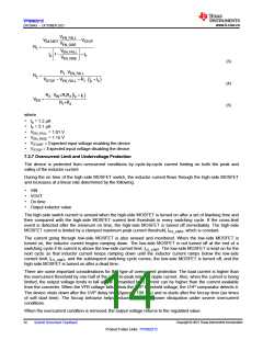
If an application requires a higher UVLO threshold on the VIN pin, the EN pin can be configured as shown in 图
7-3. When using the external UVLO function, setting the hysteresis at a value greater than 400 mV is
recommended.
The EN pin has a small pullup current, Ip, which sets the default state of the EN pin to enable when no external
components are connected. The pullup current is also used to control the voltage hysteresis for the external
UVLO function because it increases by Ih when the EN pin crosses the enable threshold. Use 方程式 3 and 方程
式 4 to calculate the values of R1 and R2 for a specified UVLO threshold. Once R1 and R2 have settled down,
the EN voltage can be calculated by 方程式5, which must be lower than 5.5 V with a maximum VIN.
VIN
Device
R1
R2
Ip
Ih
EN
图7-3. Adjustable VIN Undervoltage Lockout
Copyright © 2021 Texas Instruments Incorporated
Submit Document Feedback
13
Product Folder Links: TPS562212

 TI [ TEXAS INSTRUMENTS ]