TPS54560
www.ti.com
SLVSBN0 –MARCH 2013
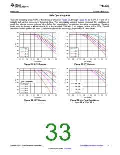
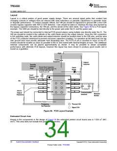
Safe Operating Area
The safe operating area (SOA) of the device is shown in Figure 56, through Figure 59 for 3.3 V, 5 V and 12 V
outputs and varying amounts of forced air flow. The temperature derating curves represent the conditions at
which the internal components are at or below the manufacturer’s maximum operating temperatures. Derating
limits apply to devices soldered directly to a double-sided PCB with 2 oz. copper, similar to the EVM. Careful
attention must be paid to the other components chosen for the design, especially the catch diode.
90
80
70
60
50
40
30
20
90
80
70
60
50
40
30
20
6 V
8 V
12 V
24 V
36 V
48 V
60 V
12 V
24 V
36 V
48 V
60 V
0.0 0.5 1.0 1.5 2.0 2.5 3.0 3.5 4.0 4.5 5.0
0.0 0.5 1.0 1.5 2.0 2.5 3.0 3.5 4.0 4.5 5.0
C047
C048
IOUT (Amps)
IOUT (Amps)
Figure 56. 3.3V Outputs
Figure 57. 5V Outputs
90
80
70
60
50
40
30
20
90
80
70
60
50
40
30
20
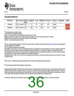
fsw = 800 kHz
400 LFM
200 LFM
100 LFM
Nat Conv
18 V
24 V
36 V
48 V
60 V
0.0 0.5 1.0 1.5 2.0 2.5 3.0 3.5 4.0 4.5 5.0
0.0 0.5 1.0 1.5 2.0 2.5 3.0 3.5 4.0 4.5 5.0
C048
C048
IOUT (Amps)
IOUT (Amps)
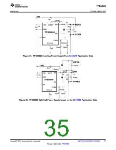
Figure 58. 12V Outputs
Figure 59. Air Flow Conditions
VIN = 36 V, VO = 12 V
Copyright © 2013, Texas Instruments Incorporated
Submit Documentation Feedback
33
Product Folder Links: TPS54560

 TI [ TEXAS INSTRUMENTS ]