TPS1HC30-Q1
ZHCSP75A –JULY 2022 –REVISED DECEMBER 2022
www.ti.com.cn
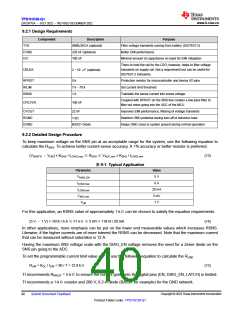
9.2.1 Design Requirements
Component
Description
Purpose
TVS
CVBB
CIC
SMBJ36CA (optional)
220 nF (optional)
100 nF
Filter voltage transients coming from battery (ISO7637-2)
Better EMI performance
Minimal amount of capacitance on input for EMI mitigation
There to hold the rail for the LDO; however, helps to filter voltage
transients on supply rail. Not a requirement but can be useful for
ISO7637-2 transients.
CBULK
2–10 μF (optional)
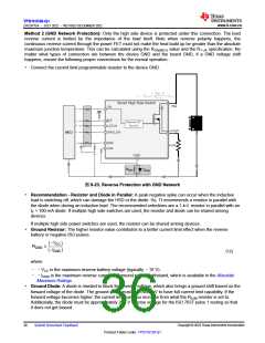
RPROT
RILIM
5 k
Protection resistor for microcontroller and device I/O pins
Set current limit threshold
7 k–70 k
1 k
RSNS
Translate the sense current into sense voltage.
Coupled with RPROT on the SNS line creates a low pass filter to
filter out noise going into the ADC of the MCU
CFILTER
100 nF
CVOUT
RGND
DGND
22 nF
Improves EMI performance, filtering of voltage transients
Stabilize GND potential during turn-off of inductive load
Keeps GND close to system ground during normal operation
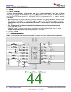
1 kΩ
BAS21 Diode
9.2.2 Detailed Design Procedure
To keep maximum voltage on the SNS pin at an acceptable range for the system, use the following equation to
calculate the RSNS. To achieve better current sense accuracy. A 1% accuracy or better resistor is preferred.
(VSNSFH –VHR) × KSNS / ILOAD,max ≤RSNS ≤VADC,min × KSNS / ILOAD,min
(13)
表9-1. Typical Application
Parameter
Value
5 V
VDIAG_EN
ILOAD,max
ILOAD,min
VADC,min
VHR
6 A
20 mA
5 mV
1 V
For this application, an RSNS value of approximately 1 kΩcan be chosen to satisfy the equation requirements.
(5 V –1 V) × 1814 / 6 A ≤≅1 kΩ≤5 mV × 11814 / 20 mA
(14)
In other applications, more emphasis can be put on the lower end measurable values which increases RSNS.
Likewise, if the higher currents are of more interest the RSNS can be decreased. Note that the maximum current
that can be measured without saturation is 12 A.
Having the maximum SNS voltage scale with the DIAG_EN voltage removes the need for a Zener diode on the
SNS pin going to the ADC.
To set the programmable current limit value at 7 A, use the following equation to calculate the RLIM
.
RLIM = KCL / ILIM = 90 / 7 = 12.8 kΩ
(15)
TI recommends RPROT = 5 kΩto ensure the current going into the digital pins (EN, DIAG_EN, LATCH) is limited.
TI recommends a 1-kΩresistor and 200-V, 0.2-A diode (BAS21 for example) for the GND network.
Copyright © 2023 Texas Instruments Incorporated
40
Submit Document Feedback
Product Folder Links: TPS1HC30-Q1

 TI [ TEXAS INSTRUMENTS ]