TMDS361B
www.ti.com
SLLS988A –SEPTEMBER 2009–REVISED JULY 2011
are four settings of the rise and fall times that can be chosen. The default setting is the fastest rise and fall
time; the other three settings are slower. Slower edge transitions can potentially help the sink system (HDTV)
in passing regulatory EMI compliance.
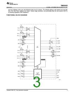
FUNCTIONAL BLOCK DIAGRAM
Vcc
RINT
RINT
Dx+_1
Dx–_1
TMDS Rx
w/ AEQ
Vcc
RINT
RINT
CLK+_1
CLK–_1
TMDS Rx
Clock Detect
VSadj
Tx
SCL1
Rx
Dx+_SINK
Dx–_SINK
TMDS Tx
Tx
SDA1
xx2
Rx
3:1
MUX
CLK+_SINK
CLK–_SINK
Vcc
TMDS Tx
RINT RINT
Dx+_3
Dx–_3
Rx
Tx
Rx
Tx
TMDS Rx
w/ AEQ
SCL_SINK
SDA_SINK
Vcc
RINT
RINT
CLK+_3
CLK–_3
TMDS Rx
Clock Detect
Clock Detect
Tx
Rx
Tx
SCL3
SDA3
Rx
HPD_SINK
I2C_SEL
LP
1 kW
1 kW
1 kW
HPD1
HPD2
HPD3
Local I2C
and
Control Logic
S1/SCL
S2/SDA
B0330-01
Copyright © 2009–2011, Texas Instruments Incorporated
3

 TI [ TEXAS INSTRUMENTS ]