TMDS261
SLLS953–DECEMBER 2008............................................................................................................................................................................................ www.ti.com
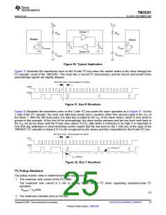
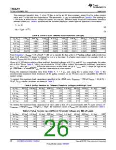
The maximum transition time, T, of an I2C bus is set by an RC time constant, where R is the pullup resistor
value and C is the total load capacitance. The parameter, k, can be calculated from Equation 3 by solving for
t, the times at which certain voltage thresholds are reached. Different input threshold combinations introduce
different values of t. Table 4 summarizes the possible values of k under different threshold combinations.
T = k × RC
V(t) = VDD(1 – e–t/RC
(2)
(3)
)
Table 4. Value of k for Different Input Threshold Voltages
Vth–\Vth+
0.1 VDD
0.15 VDD
0.2 VDD
0.25 VDD
0.3 VDD
0.7 VDD
1.0986
1.0415
0.9808
0.9163
0.8473
0.65 VDD
0.9445
0.8873
0.8267
0.7621
0.6931
0.6 VDD
0.8109
0.7538
0.6931
0.6286
0.5596
0.55 VDD
0.6931
0.6360
0.5754
0.5108
0.4418
0.5 VDD
0.5878
0.5306
0.4700
0.4055
0.3365
0.45 VDD
0.4925
0.4353
0.3747
0.3102
0.2412
0.4 VDD
0.4055
0.3483
0.2877
0.2231
0.1542
0.35 VDD
0.3254
0.2683
0.2076
0.1431
0.0741
0.3 VDD
0.2513
0.1942
0.1335
0.0690
—
From Equation 1, Rup(min) = 5.5 V/3 mA = 1.83 kΩ to operate the bus under a 5-V pullup voltage and provide less
than 3 mA when the I2C device is driving the bus to a low state. If a higher sink current, for example 4 mA, is
allowed, Rup(min) can be as low as 1.375 kΩ.
Given a 5-V I2C device with input low and high threshold voltages at 0.3 Vdd and 0.7 Vdd, respectively, the value
of k is 0.8473 from Table 4. Taking into account the 1.83-kΩ pullup resistor, the maximum total load capacitance
is C(total-5V) = 645 pF. Ccable(max) should be restricted to be less than 545 pF if Csource and Ci can be as high as 50
pF. Here the Ci is treated as Csink, the load capacitance of a sink device.
Fixing the maximum transition time from Table 4, T = 1 µs, and using the k values from Table 4, the
recommended maximum total resistance of the pullup resistors on an I2C bus can be calculated for different
system setups.
To support the maximum load capacitance specified in the HDMI spec, Ccable(max) = 700 pF/Csource = 50 pF/Ci =
50 pF, R(max) can be calculated as shown in Table 5.
Table 5. Pullup Resistor for Different Threshold Voltages and 800-pF Load
Vth–\Vth+
0.1 VDD
0.15 VDD
0.2 VDD
0.25 VDD
0.3 VDD
0.7 VDD
1.14
0.65 VDD
1.32
0.6 VDD
1.54
0.55 VDD
1.80
0.5 VDD
2.13
0.45 VDD
2.54
0.4 VDD
3.08
0.35 VDD
3.84
0.3 VDD
4.97
6.44
9.36
18.12
—
UNIT
kΩ
1.20
1.41
1.66
1.97
2.36
2.87
3.59
4.66
kΩ
1.27
1.51
1.80
2.17
2.66
3.34
4.35
6.02
kΩ
1.36
1.64
1.99
2.45
3.08
4.03
5.60
8.74
kΩ
1.48
1.80
2.23
2.83
3.72
5.18
8.11
16.87
kΩ
Or, limiting the maximum load capacitance of each cable to 400 pF to accommodate with I2C spec version 2.1.
Ccable(max) = 400 pF/Csource = 50 pF/Ci = 50 pF, the maximum values of R(max) are calculated as shown in Table 6.
Table 6. Pullup Resistor Upon Different Threshold Voltages and 500-pF Loads
Vth–\Vth+
0.1 VDD
0.15 VDD
0.2 VDD
0.25 VDD
0.3 VDD
0.7 VDD
1.82
0.65 VDD
2.12
0.6 VDD
2.47
0.55 VDD
2.89
0.5 VDD
3.40
0.45 VDD
4.06
0.4 VDD
4.93
0.35 VDD
6.15
0.3 VDD
7.96
UNIT
kΩ
1.92
2.25
2.65
3.14
3.77
4.59
5.74
7.46
10.30
14.98
28.99
—
kΩ
2.04
2.42
2.89
3.48
4.26
5.34
6.95
9.63
kΩ
2.18
2.62
3.18
3.92
4.93
6.45
8.96
13.98
26.99
kΩ
2.36
2.89
3.57
4.53
5.94
8.29
12.97
kΩ
26
Submit Documentation Feedback
Copyright © 2008, Texas Instruments Incorporated
Product Folder Link(s) :TMDS261

 TI [ TEXAS INSTRUMENTS ]