TMDS261
SLLS953–DECEMBER 2008............................................................................................................................................................................................ www.ti.com
AVCC(4)
(5)
R
R
T
T
<2-inch(6) 50-W
Transmission Line
SMA
SMA
SMA
SMA
Coax
Coax
Coax
Coax
Data+
Data–
RX
+EQ
OUT
<2-inch(6) 50-W
Transmission Line
Video
Patterm
Generator
Jitter Test
(2, 3)
Instrument
HDMI Cable(1)
AVCC
TM261
1000-mVpp
Differential
R
T
R
T
<2-inch(6) 50-W
Transmission Line
SMA
SMA
SMA
SMA
Coax
Coax
Coax
Coax
Clk+
Clk–
RX
+EQ
OUT
<2-inch(6) 50-W
Transmission Line
Jitter Test
(2, 3)
Instrument
TTP4
TTP1
TTP2
TTP3
B0331-02
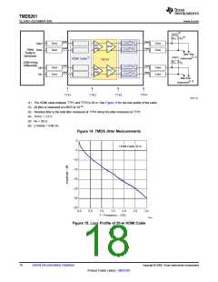
(1) The HDMI cable between TTP1 and TTP2 is 20 m. See Figure 15 for the loss profile of the cable.
(2) All jitter is measured at a BER of 10–12
.
(3) Residual jitter is the total jitter measured at TTP4 minus the jitter measured at TTP1.
(4) AVCC = 3.3 V.
(5) RT = 50 Ω.
(6) 2 inches = 5.08 cm.
Figure 14. TMDS Jitter Measurements
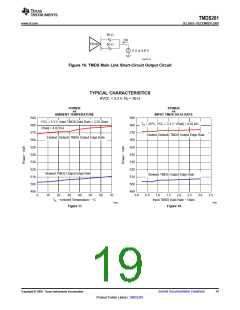
0
HDMI Cable 20 m
−5
−10
−15
−20
−25
−30
−35
0.0
0.5
1.0
1.5
2.0
2.5
3.0
f − Frequency − GHz
G001
Figure 15. Loss Profile of 20-m HDMI Cable
18
Submit Documentation Feedback
Copyright © 2008, Texas Instruments Incorporated
Product Folder Link(s) :TMDS261

 TI [ TEXAS INSTRUMENTS ]