ꢀ ꢁꢂꢃ ꢄ ꢅ ꢆꢇ ꢈꢉꢉꢅ ꢃ
SLAS356 − DECEMBER 2001
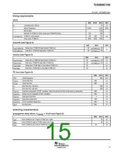
timing requirements
clock
MIN NOM
MAX
10
UNIT
ns
t
t
Transition time, MCLK
MCLK frequency
2.048
2.048
37%
256
MHz
MCLK jitter
Number of PCMCLK clock cycles per PCMSYN frame
PCMCLK clock period
256
156
t
488
512
ns
c(PCMCLK)
Duty cycle, PCMCLK
45%
50%
68%
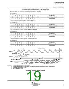
transmit (see Figure 6)
MIN
MAX
UNIT
t
t
Setup time, PCMSYN high before PCMCLK↓
Hold time, PCMSYN high after PCMCLK↓
20
20
t
t
−20
−20
su(PCMSYN)
c(PCMCLK)
ns
h(PCMSYN)
c(PCMCLK)
receive (see Figure 5)
MIN
MAX
UNIT
ns
t
t
t
t
Setup time, PCMSYN high before PCMCLK↓
Hold time, PCMSYN high after PCMCLK↓
Setup time, PCMI high or low before PCMCLK↓
Hold time, PCMI high or low after PCMCLK↓
20
20
20
20
t
t
−20
−20
su(PCSYN)
h(PCSYN)
su(PCMI)
h(PCMI)
c(PCMCLK)
ns
c(PCMCLK)
ns
ns
2
I C bus (see Figure 6)
MIN
MAX
UNIT
kHz
ns
SCL
Clock frequency
400
t
t
t
t
t
t
t
t
t
t
Clock high time
600
HIGH
LOW
r
Clock low time
1300
ns
SDA and SCL rise time
300
300
ns
SDA and SCL fall time
ns
f
Hold time (repeated) START condition. After this period the first clock pulse is generated.
600
600
0
ns
h(STA)
su(STA)
h(DAT)
su(DAT)
su(STO)
BUF
Setup time for repeated START condition
Data input hold time
ns
ns
Data input setup time
100
600
1300
ns
STOP condition setup time
Bus free time
ns
ns
switching characteristics
propagation delay times, C
= 10 pF (see Figure 5)
L(max)
MIN
MAX
35
UNIT
ns
t
t
t
From PCMCLK bit 1 high to PCMO bit 1 valid
From PCMCLK high to PCMO valid, bits 2 to n
From PCMCLK bit n low to PCMO bit n Hi-Z
pd1
pd2
pd3
35
ns
30
ns
15
www.ti.com

 TI [ TEXAS INSTRUMENTS ]