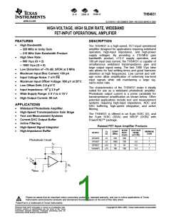
THS4631
www.ti.com
SLOS451A–DECEMBER 2004–REVISED MARCH 2005
This integrated circuit can be damaged by ESD. Texas Instruments recommends that all integrated
circuits be handled with appropriate precautions. Failure to observe proper handling and installation
procedures can cause damage.
ESD damage can range from subtle performance degradation to complete device failure. Precision
integrated circuits may be more susceptible to damage because very small parametric changes could
cause the device not to meet its published specifications.
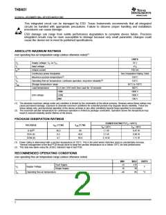
ABSOLUTE MAXIMUM RATINGS
over operating free-air temperature range (unless otherwise noted)(1)
UNITS
VS
VI
Supply voltage, VS– to VS+
33 V
Input voltage
±VS
(2)
IO
Output current
150 mA
Continuous power dissipation
Maximum junction temperature(2)
Operating free-air temperature, continues operation, long-term reliability(2)
Storage temperature range
See Dissipation Rating Table
TJ
150°C
125°C
TA
Tstg
65°C to 150°C
300°C
Lead temperature
1,6 mm (1/16 inch) from case for 10 seconds
HBM
CDM
MM
1000 V
ESD ratings:
1500 V
100 V
(1) The absolute maximum ratings under any condition is limited by the constraints of the silicon process. Stresses above these ratings may
cause permanent damage. Exposure to absolute maximum conditions for extended periods may degrade device reliability. These are
stress ratings only, and functional operation of the device at these or any other conditions beyond those specified is not implied.
(2) The maximum junction temperature for continuous operation is limited by package constraints. Operation above this temperature may
result in reduced reliability and/or lifetime of the device.
PACKAGE DISSIPATION RATINGS
POWER RATING(1) (TJ =125°C)
PACKAGE
θJC (°C/W)
θJA (°C/W)
T
A ≤ 25°C
TA = 85°C
0.47 W
D (8)(2)
DDA (8)
DGN (8)
38.3
9.2
95
1.1 W
45.8
58.4
2.3 W
0.98 W
4.7
2.14 W
1.11 W
(1) Power rating is determined with a junction temperature of 125°C. This is the point where distortion starts to substantially increase.
Thermal management of the final PCB should strive to keep the junction temperature at or below 125°C for best performance.
(2) This data was taken using the JEDEC standard High-K test PCB.
RECOMMENDED OPERATING CONDITIONS
over operating free-air temperature range (unless otherwise noted)
MIN
±5
MAX
±15
30
UNITS
V
Dual Supply
VS
TA
Supply Voltage
Single Supply
10
Operating free-air temperature
-40
85
°C
2

 TI [ TEXAS INSTRUMENTS ]