TAS5715
www.ti.com
SLOS645 –AUGUST 2010
overloaded, a second protection system triggers a latching shutdown, resulting in the power stage being set in
the high-impedance (Hi-Z) state. The device returns to normal operation once the fault condition (i.e., a short
circuit on the output) is removed. Current limiting and overcurrent protection are not independent for half-bridges.
That is, if the bridge-tied load between half-bridges A and B causes an overcurrent fault, half-bridges A, B, C,
and D are shut down.
Overtemperature Protection
The TAS5715 has an overtemperature-protection system. If the device junction temperature exceeds 150°C
(nominal), the device is put into thermal shutdown, resulting in all half-bridge outputs being set in the
high-impedance (Hi-Z) state and FAULT being asserted low. The TAS5715 recovers automatically once the
temperature drops approximately 30°.
Undervoltage Protection (UVP) and Power-On Reset (POR)
The UVP and POR circuits of the TAS5715 fully protect the device in any power-up/down and brownout situation.
While powering up, the POR circuit resets the overload circuit (OLP) and ensures that all circuits are fully
operational when the PVDD and AVDD supply voltages reach 7.6 V and 2.7 V, respectively. Although PVDD and
AVDD are independently monitored, a supply voltage drop below the UVP threshold on AVDD or on either PVDD
pin results in all half-bridge outputs immediately being set in the high-impedance (Hi-Z) state and FAULT being
asserted low.
SSTIMER FUNCTIONALITY
SSTIMER is used to reduced turnon pop. This is used only in AD mode. The SSTIMER pin uses a capacitor
connected between this pin and ground to control the output duty cycle when exiting all-channel shutdown. The
capacitor on the SSTIMER pin is slowly charged through an internal current source, and the charge time
determines the rate at which the output transitions from a near-zero duty cycle to the desired duty cycle. This
allows for a smooth transition that minimizes audible pops and clicks. When the part is shut down, the drivers are
high-impedance and transition slowly down through a 3-kΩ resistor, similarly minimizing pops and clicks. The
shutdown transition time is independent of the SSTIMER pin capacitance. Larger capacitors increase the start-up
time, whereas capacitors smaller than 2.2 nF decrease the start-up time. The SSTIMER pin should be left
floating for BD modulation.
CLOCK, AUTO DETECTION, AND PLL
The TAS5715 is a slave device. It accepts MCLK, SCLK, and LRCLK. The digital audio processor (DAP)
supports all the sample rates and MCLK rates that are defined in the clock control register .
The TAS5715 checks to verify that SCLK is a specific value of 32 fS, 48 fS, or 64 fS. The DAP only supports a 1 ×
fS LRCLK. The timing relationship of these clocks to SDIN is shown in subsequent sections. The clock section
uses MCLK or the internal oscillator clock (when MCLK is unstable, out of range, or absent) to produce the
internal clock (DCLK) running at 512 times the PWM switching frequency.
The DAP can autodetect and set the internal clock-control logic to the appropriate settings for all supported clock
rates as defined in the clock control register.
TAS5715 has robust clock error handling that uses the bulit-in trimmed oscillator clock to quickly detect
changes/errors. Once the system detects a clock change/error, it mutes the audio (through a single-step mute)
and then forces PLL to limp using the internal oscillator as a reference clock. Once the clocks are stable, the
system autodetects the new rate and reverts to normal operation. During this process, the default volume is
restored in a single step (also called hard unmute). The ramp process can be programmed to ramp back slowly
(also called soft unmute) as defined in volume register (0x0E).
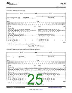
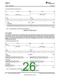
SERIAL DATA INTERFACE
Serial data is input on SDIN. The PWM outputs are derived from SDIN. The TAS5715 DAP accepts serial data in
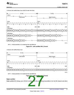
16-, 20-, or 24-bit left-justified, right-justified, or I2S serial data format.
Copyright © 2010, Texas Instruments Incorporated
Submit Documentation Feedback
23
Product Folder Link(s): TAS5715

 TI [ TEXAS INSTRUMENTS ]