TAS5727
SLOS670 –NOVEMBER 2010
www.ti.com
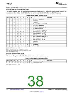
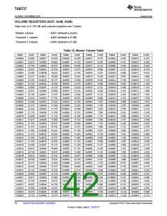
CLOCK CONTROL REGISTER (0x00)
The clocks and data rates are automatically determined by the TAS5727. The clock control register contains the
autodetected clock status. Bits D7–D5 reflect the sample rate. Bits D4–D2 reflect the MCLK frequency.
Table 5. Clock Control Register (0x00)
D7
0
0
0
0
1
1
1
1
–
–
–
–
–
–
–
–
–
–
D6
0
0
1
1
0
0
1
1
–
–
–
–
–
–
–
–
–
–
D5
0
1
0
1
0
1
0
1
–
–
–
–
–
–
–
–
–
–
D4
–
–
–
–
–
–
–
–
0
0
0
0
1
1
1
1
–
–
D3
–
–
–
–
–
–
–
–
0
0
1
1
0
0
1
1
–
–
D2
–
–
–
–
–
–
–
–
0
1
0
1
0
1
0
1
–
–
D1
–
–
–
–
–
–
–
–
–
–
–
–
–
–
–
–
0
–
D0
–
–
–
–
–
–
–
–
–
–
–
–
–
–
–
–
–
0
FUNCTION
fS = 32-kHz sample rate
Reserved
Reserved
fS = 44.1/48-kHz sample rate(1)
fS = 16-kHz sample rate
fS = 22.05/24-kHz sample rate
fS = 8-kHz sample rate
fS = 11.025/12-kHz sample rate
(2)
MCLK frequency = 64 × fS
(2)
MCLK frequency = 128 × fS
(3)
MCLK frequency = 192 × fS
(1)(4)
MCLK frequency = 256 × fS
MCLK frequency = 384 × fS
MCLK frequency = 512 × fS
Reserved
Reserved
Reserved(1)
Reserved(1)
(1) Default values are in bold.
(2) Only available for 44.1-kHz and 48-kHz rates
(3) Rate only available for 32/44.1/48-KHz sample rates
(4) Not available at 8 kHz
DEVICE ID REGISTER (0x01)
The device ID register contains the ID code for the firmware revision.
Table 6. General Status Register (0x01)
D7
0
D6
0
D5
0
D4
0
D3
0
D2
0
D1
0
D0
0
FUNCTION
Identification code(1)
(1) Default values are in bold.
38
Submit Documentation Feedback
Copyright © 2010, Texas Instruments Incorporated
Product Folder Link(s): TAS5727

 TI [ TEXAS INSTRUMENTS ]