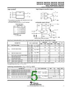
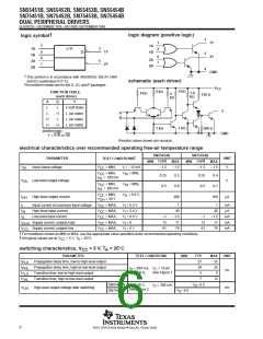
SN55451B, SN55452B, SN55453B, SN55454B
SN75451B, SN75452B, SN75453B, SN75454B
DUAL PERIPHERAL DRIVERS
SLRS021B – DECEMBER 1976 – REVISED SEPTEMBER 1999
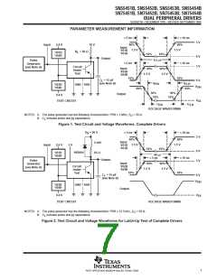
PARAMETER MEASUREMENT INFORMATION
≤ 5 ns
90%
≤ 10 ns
3 V
Input
2.4 V
10 V
90%
1.5 V
Input
1.5 V
’451B
’453B
R
= 50 Ω
L
’451B
’452B
10%
90%
10%
0.5 µs
0 V
3 V
Output
Pulse
Generator
(see Note A)
≤ 5 ns
≤ 10 ns
Circuit
Under
Test
Input
’452B
’454B
90%
1.5 V
1.5 V
10%
10%
C
= 15 pF
0 V
L
t
t
(see Note B)
PHL
PLH
90%
’453B
’454B
GND SUB
V
OH
90%
50%
10%
50%
10%
Output
0.4 V
V
OL
TEST CIRCUIT
t
t
TLH
THL
VOLTAGE WAVEFORMS
NOTES: A. The pulse generator has the following characteristics: PRR ≤ 1 MHz, Z = 50 Ω.
O
B.
C includes probe and jig capacitance.
L
Figure 1. Test Circuit and Voltage Waveforms, Complete Drivers
V
S
= 20 V
≤ 5 ns
90%
≤ 10 ns
3 V
90%
1.5 V
Input
2 mH
1.5 V
Input
2.4 V
5 V
’451B
’453B
10%
10%
40 µs
0 V
3 V
1N3064
’451B
’452B
65 Ω
≤ 5 ns
90%
1.5 V
≤ 10 ns
Output
Pulse
Generator
(see Note A)
Input
’452B
’454B
90%
1.5 V
Circuit
Under
Test
10%
10%
C
= 15 pF
0 V
L
(see Note B)
V
OH
’453B
’454B
GND SUB
Output
0.4 V
V
OL
TEST CIRCUIT
VOLTAGE WAVEFORMS
NOTES: A. The pulse generator has the following characteristics: PRR ≤ 12.5 kHz, Z = 50 Ω.
O
B.
C includes probe and jig capacitance.
L
Figure 2. Test Circuit and Voltage Waveforms for Latch-Up Test of Complete Drivers
7
POST OFFICE BOX 655303 • DALLAS, TEXAS 75265

 TI [ TEXAS INSTRUMENTS ]