Application Notes
PT6100/6210/6300 Series
Figure 1
Using the Inhibit Function on Power Trends’
Wide Input Range Bus ISRs
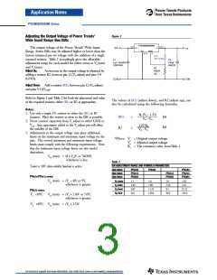
For applications requiring output voltage On/Off con-
trol, the 12pin ISR products incorporate an inhibit function.
The function has uses in areas such as battery conservation,
power-up sequencing, or any other application where the
regulated output from the module is required to be switched
off. The On/Off function is provided by the Pin 1 (Inhibit)
control.
PT6100/6210/6300
2,3,4
9,10,11
Vin
Vo
Vin
Vout
GND
Vo(adj)
12
Inh*
1
5,6,7,8
+
C1, 1
(Optional)
µ
F
C2
100
µ
F
Q1
BSS138
Inh
The ISR functions normally with Pin 1 open-circuit,
providing a regulated output whenever a valid source voltage
is applied to Vin, (pins 2, 3, & 4). When a low-level2 ground
signal is applied to Pin 1, the regulator output will be dis-
abled.
C O M
C O M
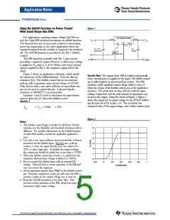
Figure 1 shows an application schematic, which details
the typical use of the Inhibit function. Note the discrete
transistor (Q1). The Inhibit control has its own internal
pull-up with a maximum open-circuit voltage of 8.3VDC.
Only devices with a true open-collector or open-drain out-
put can be used to control this pin. A discrete bipolar
transistor or MOSFET is recommended.
Turn-On Time: The output of the ISR is enabled automatically
when external power is applied to the input. The Inhibit control
pin is pulled high by its internal pull-up resistor. The ISR
produces a fully regulated output voltage within 1-msec of
either the release of the Inhibit control pin, or the application
of power. The actual turn-on time will vary with the input
voltage, output load, and the total amount of capacitance con-
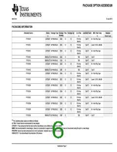
nected to the output Using the circuit of Figure 1, Figure 2
shows the typical rise in output voltage for the PT6101 follow-
ing the turn-off of Q1 at time t =0. The waveform was
measured with a 9Vdc input voltage, and 5-Ohm resistive load.
Equation 1 may be used to determine the approximate
current drawn by Q1 when the inhibit is active.
Equation 1
Istby
= Vin ÷ 155kΩ
20%
Figure 2
Notes:
1. The Inhibit control logic is similar for all Power Trends’
modules, but the flexibility and threshold tolerances will be
different. For specific information on the inhibit function
of other ISR models, consult the applicable application
note.
2. Use only a true open-collector device (preferably a discrete
transistor) for the Inhibit input. Do Not use a pull-up
resistor, or drive the input directly from the output of a
TTL or other logic gate. To disable the output voltage,
the control pin should be pulled low to less than +1.5VDC.
3. When the Inhibit control pin is active, i.e. pulled low, the
maximum allowed input voltage is limited to +30Vdc.
4. Do not control the Inhibit input with an external DC
voltage. This will lead to erratic operation of the ISR and
may over-stress the regulator.
6
5
4
3
2
1
0
-0.2
0
0.2
0.4
0.6
0.8
1
t (milli-secs)
5. Avoid capacitance greater than 500pF at the Inhibit control
pin. Excessive capacitance at this pin will cause the ISR to
produce a pulse on the output voltage bus at turn-on.
6. Keep the On/Off transition to less than 10µs. This
prevents erratic operation of the ISR, which can cause a
momentary high output voltage.
For technical support and more information, see inside back cover or visit www.ti.com/powertrends

 TI [ TEXAS INSTRUMENTS ]