Application Notes
PT6100/6210/6300 Series
Figure 1
Vin
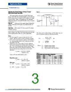
Adjusting the Output Voltage of Power Trends’
Wide Input Range Bus ISRs
PT6100/6200/6300
2,3,4
9,10,11
Vin
Vo
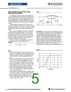
The output voltage of the Power Trends’ Wide Input
Range Series ISRs may be adjusted higher or lower than the
factory trimmed pre-set voltage with the addition of a single
external resistor. Table 1 accordingly gives the allowable
adjustment range for each model for either series as Va (min)
and Va (max).
Vo
GND
5,6,7,8
Vo(adj)
12
(R1)
Adj Down
C1
C2
100µF
(Req’d)
+
1
µ
F Ceramic
(Optional)
R2
Adjust
Up
Adjust Up:
An increase in the output voltage is obtained by
adding a resistor R2, between pin 12 (Vo adjust) and pins 5-8
(GND).
COM
COM
Adjust Down: Add a resistor (R1), between pin 12 (Vo adjust)
and pins 9-11(Vout).
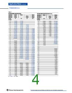
Refer to Figure 1 and Table 2 for both the placement and value
of the required resistor; either (R1) or R2 as appropriate.
The values of (R1) [adjust down], and R2 [adjust up], can
also be calculated using the following formulae.
Notes:
1. Use only a single 1% resistor in either the (R1) or R2
location. Place the resistor as close to the ISR as possible.
2. Never connect capacitors from Vo adjust to either GND or
Vout. Any capacitance added to the Vo adjust pin will affect
the stability of the ISR.
Ro (Va – 1.25)
(R1)
R2
=
=
kΩ
kΩ
Vo – Va
1.25 Ro
Va – Vo
3. Adjustments to the output voltage may place additional
limits on the maximum and minimum input voltage for the
part. The revised maximum and minimum input voltage
limits must comply with the following requirements. Note
that the minimum input voltage limits are also model
dependant.
Where: Vo = Original output voltage
Va = Adjusted output voltage
Ro = The resistance value fromTable 1
Vin (max) = (8 x Va)V or *30/38V,
whichever is less.
Table 1
ISR ADJUSTMENT RANGE AND FORMULA PARAMETERS
*Limit is 30V when inhibit function is active.
1Adc Rated
2Adc Rated
3Adc Rated
PT6102
PT6213
PT6303
PT6101
PT6103
PT6214
PT6304
PT6212
PT6302
PT6x0x/PT6x1x series:
Vin (min) = (Va + 4)V or 9V,
whichever is greater.
V (nom)
3.3
5.0
5.0
12.0
o
V (min)
a
1.89
6.07
66.5
1.88
11.25
150.0
2.18
8.5
2.43
V (max)
a
22.12
243.0
PT6x2x series:
R
o
(kΩ)
90.9
Vo <10V;
Vin (min) = (Va + 2.0)V or 7.0V,
whichever is greater.
Vo ≥10V;
Vin (min) = (Va + 2.5)V
For technical support and more information, see inside back cover or visit www.ti.com/powertrends

 TI [ TEXAS INSTRUMENTS ]