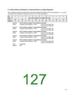
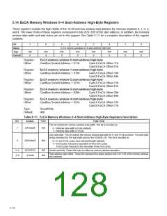
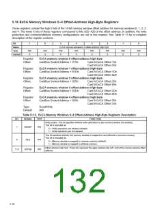
5.14 ExCA Memory Windows 0−4 Start-Address High-Byte Registers
These registers contain the high nibble of the 16-bit memory window start address for memory windows 0, 1, 2, 3,
and 4. The lower 4 bits of these registers correspond to bits A23−A20 of the start address. In addition, the memory
window data width and wait states are set in this register. See Table 5−11 for a complete description of the register
contents.
Bit
7
6
5
4
3
2
1
0
Name
Type
Default
ExCA memory windows 0−4 start-address high-byte
RW
0
RW
0
RW
0
RW
0
RW
0
RW
0
RW
0
RW
0
Register:
Offset:
ExCA memory window 0 start-address high-byte
CardBus Socket Address + 811h:
Card A ExCA Offset 11h
Card B ExCA Offset 51h
Register:
Offset:
ExCA memory window 1 start-address high-byte
CardBus Socket Address + 819h: Card A ExCA Offset 19h
Card B ExCA Offset 59h
ExCA memory window 2 start-address high-byte
CardBus Socket Address + 821h: Card A ExCA Offset 21h
Card B ExCA Offset 61h
ExCA memory window 3 start-address high-byte
CardBus Socket Address + 829h: Card A ExCA Offset 29h
Card B ExCA Offset 69h
ExCA memory window 4 start-address high-byte
Register:
Offset:
Register:
Offset:
Register:
Offset:
CardBus Socket Address + 831h:
Card A ExCA Offset 31h
Card B ExCA Offset 71h
Type:
Default:
Read/Write
00h
Table 5−11. ExCA Memory Windows 0−4 Start-Address High-Byte Registers Description
BIT
SIGNAL
TYPE
FUNCTION
This bit controls the memory window data width. This bit is encoded as:
7
DATASIZE
RW
0 = Window data width is 8 bits (default)
1 = Window data width is 16 bits
Zero wait-state. This bit controls the memory window wait state for 8- and 16-bit accesses. This wait-state
timing emulates the ISA wait state used by the 82365SL-DF. This bit is encoded as:
6
ZEROWAIT
RW
0 = 8- and 16-bit cycles have standard length (default).
1 = 8-bit cycles reduced to equivalent of three ISA cycles
16-bit cycles reduced to the equivalent of two ISA cycles
5−4
3−0
SCRATCH
STAHN
RW
RW
Scratch pad bits. These bits have no effect on memory window operation.
Start address high-nibble. These bits represent the upper address bits A23−A20 of the memory window
start address.
5−16

 TI [ TEXAS INSTRUMENTS ]