OMAP-L137 Low-Power Applications Processor
SPRS563A–SEPTEMBER 2008–REVISED OCTOBER 2008
www.ti.com
Table 6-65. ECAPx Configuration Registers (continued)
ECAP0
BYTE ADDRESS
ECAP1
ECAP2
REGISTER NAME
DESCRIPTION
BYTE ADDRESS
0x01F0 700C
0x01F0 7010
0x01F0 7014
0x01F0 7028
0x01F0 702A
0x01F0 702C
0x01F0 702E
0x01F0 7030
0x01F0 7032
0x01F0 705C
BYTE ADDRESS
0x01F0 800C
0x01F0 8010
0x01F0 8014
0x01F0 8028
0x01F0 802A
0x01F0 802C
0x01F0 802E
0x01F0 8030
0x01F0 8032
0x01F0 805C
0x01F0 600C
0x01F0 6010
0x01F0 6014
0x01F0 6028
0x01F0 602A
0x01F0 602C
0x01F0 602E
0x01F0 6030
0x01F0 6032
0x01F0 605C
CAP2
CAP3
Capture 2 Register
Capture 3 Register
CAP4
Capture 4 Register
ECCTL1
ECCTL2
ECEINT
ECFLG
ECCLR
ECFRC
REVID
Capture Control Register 1
Capture Control Register 2
Capture Interrupt Enable Register
Capture Interrupt Flag Register
Capture Interrupt Clear Register
Capture Interrupt Force Register
Revision ID
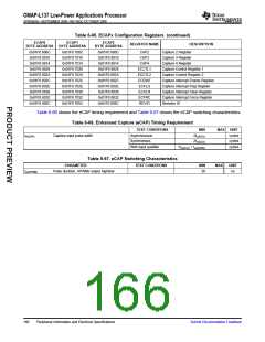
Table 6-66 shows the eCAP timing requirement and Table 6-67 shows the eCAP switching characteristics.
Table 6-66. Enhanced Capture (eCAP) Timing Requirement
TEST CONDITIONS
Asynchronous
MIN
2tc(SCO)
MAX UNIT
cycles
tw(CAP)
Capture input pulse width
Synchronous
2tc(SCO)
cycles
With input qualifier
1tc(SCO) + tw(IQSW)
cycles
Table 6-67. eCAP Switching Characteristics
PARAMETER
Pulse duration, APWMx output high/low
TEST CONDITIONS
MIN
MAX
UNIT
tw(APWM)
20
ns
166
Peripheral Information and Electrical Specifications
Submit Documentation Feedback

 TI [ TEXAS INSTRUMENTS ]