LT1007, LT1007A, LT1037, LT1037A
LOW-NOISE, HIGH-SPEED, PRECISION OPERATIONAL AMPLIFIERS
SLOS017C – D3195, FEBRUARY 1989 – REVISED JANUARY 1993
APPLICATION INFORMATION
noise testing
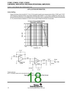
Figure 39 shows a test circuit for 0.1-Hz to 10-Hz peak-to-peak noise measurement of the LT1007 and LT1037.
The frequency response of this noise tester indicates that eeethe 0.1 Hz corner is defined by only one zero.
Because the time limit acts as an additional zero to eliminate noise contributions from the frequency band below
0.1 Hz, the test time to measure 0.1-Hz to 10-Hz noise should not exceed 10 seconds.
0.1 Hz to 10 Hz p-p NOISE TESTER
FREQUENCY RESPONSE
100
90
80
70
60
50
40
30
0.01
0.1
1
10
100
Frequency – Hz
0.1 µF
100 kΩ
10 Ω
–
2 kΩ
†
+
+
22 µF
Scope
x 1
4.3 kΩ
LT1001
4.7 µF
R
= 1 MΩ
IN
Voltage Gain
= 50,000
–
2.2 µF
110 kΩ
100 kΩ
24.3 kΩ
0.1 µF
†
Device under test
NOTE: All capacitor values are for non-polarized capacitors only.
Figure 39. 0.1-Hz To 10-Hz Noise Test Circuit
18
POST OFFICE BOX 655303 • DALLAS, TEXAS 75265

 TI [ TEXAS INSTRUMENTS ]