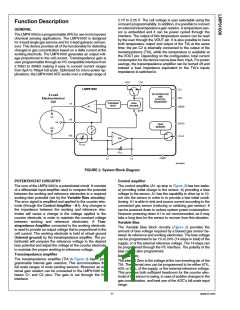
The Internal zero is provided through an internal voltage di-
vider (Vref divider box in Figure 2). The divider is programmed
through the I2C interface.
-2
-1
0
1576
1568
1560
1552
1544
1536
1528
1520
1512
1504
1496
1488
1480
1472
1464
1456
1448
1440
1432
1424
1415
1407
1399
1391
1383
61
62
63
64
65
66
67
68
69
70
71
72
73
74
75
76
77
78
79
80
81
82
83
84
85
1063
1054
1046
1038
1029
1021
1012
1004
996
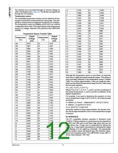
Temperature sensor
1
The embedded temperature sensor can be switched off dur-
ing gas concentration measurement to save power. The tem-
perature measurement is triggered through the I2C interface.
The temperature output is available at the VOUT pin until the
configuration bit is reset. The output signal of the temperature
sensor is a voltage, referred to the ground of the LMP91000
(AGND).
2
3
4
5
6
7
987
Temperature Sensor Transfer Table
8
979
Output
Voltage
(mV)
Output
Voltage
(mV)
Temperature
(°C)
Temperature
(°C)
9
971
10
11
12
13
14
15
16
17
18
19
20
21
22
962
-40
-39
-38
-37
-36
-35
-34
-33
-32
-31
-30
-29
-28
-27
-26
-25
-24
-23
-22
-21
-20
-19
-18
-17
-16
-15
-14
-13
-12
-11
-10
-9
1875
23
24
25
26
27
28
29
30
31
32
33
34
35
36
37
38
39
40
41
42
43
44
45
46
47
48
49
50
51
52
53
54
55
56
57
58
59
60
1375
954
1867
1860
1852
1844
1836
1828
1821
1813
1805
1797
1789
1782
1774
1766
1758
1750
1742
1734
1727
1719
1711
1703
1695
1687
1679
1671
1663
1656
1648
1640
1632
1624
1616
1608
1600
1592
1584
1367
1359
1351
1342
1334
1326
1318
1310
1302
1293
1285
1277
1269
1261
1253
1244
1236
1228
1220
1212
1203
1195
1187
1179
1170
1162
1154
1146
1137
1129
1121
1112
1104
1096
1087
1079
1071
945
937
929
920
912
903
895
886
878
870
861
Although the temperature sensor is very linear, its response
does have a slight downward parabolic shape. This shape is
very accurately reflected in the temperature sensor Transfer
Table. For a linear approximation, a line can easily be calcu-
lated over the desired temperature range from the Table using
the two-point equation:
V-V1=((V2–V1)/(T2–T1))*(T-T1)
Where V is in mV, T is in °C, T1 and V1 are the coordinates of
the lowest temperature, T2 and V2 are the coordinates of the
highest temperature.
For example, if we want to determine the equation of a line
over a temperature range of 20°C to 50°C, we would proceed
as follows:
V-1399mV=((1154mV - 1399mV)/(50°C -20°C))*(T-20°C)
V-1399mV= -8.16mV/°C*(T-20°C)
V=(-8.16mV/°C)*T+1562.2mV
Using this method of linear approximation, the transfer func-
tion can be approximated for one or more temperature ranges
of interest.
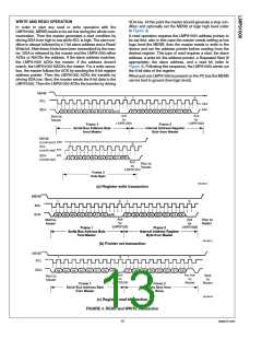
I2C INTERFACE
The I2C compatible interface operates in Standard mode
(100kHz). Pull-up resistors or current sources are required on
the SCL and SDA pins to pull them high when they are not
being driven low. A logic zero is transmitted by driving the
output low. A logic high is transmitted by releasing the output
and allowing it to be pulled-up externally. The appropriate
pull-up resistor values will depend upon the total bus capac-
itance and operating speed. The LMP91000 comes with a 7
bit bus fixed address: 1001 000.
-8
-7
-6
-5
-4
-3
www.ti.com
12

 TI [ TEXAS INSTRUMENTS ]