2.7V to 5.25 V. The cell voltage is user selectable using the
on board programmability. In addition, it is possible to connect
an external transimpedance gain resistor. A temperature sen-
sor is embedded and it can be power cycled through the
interface. The output of this temperature sensor can be read
by the user through the VOUT pin. It is also possible to have
both temperature output and output of the TIA at the same
time; the pin C2 is internally connected to the output of the
transimpedance (TIA), while the temperature is available at
the VOUT pin. Depending on the configuration, total current
consumption for the device can be less than 10µA. For power
savings, the transimpedance amplifier can be turned off and
instead a load impedance equivalent to the TIA’s inputs
impedance is switched in.
Function Description
GENERAL
The LMP91000 is a programmable AFE for use in micropower
chemical sensing applications. The LMP91000 is designed
for 3-lead single gas sensors and for 2-lead galvanic cell sen-
sors. This device provides all of the functionality for detecting
changes in gas concentration based on a delta current at the
working electrode. The LMP91000 generates an output volt-
age proportional to the cell current. Transimpedance gain is
user programmable through an I2C compatible interface from
2.75kΩ to 350kΩ making it easy to convert current ranges
from 5µA to 750µA full scale. Optimized for micro-power ap-
plications, the LMP91000 AFE works over a voltage range of
30132583
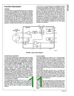
FIGURE 2. System Block Diagram
POTENTIOSTAT CIRCUITRY
Control amplifier
The core of the LMP91000 is a potentiostat circuit. It consists
of a differential input amplifier used to compare the potential
between the working and reference electrodes to a required
working bias potential (set by the Variable Bias circuitry).
The error signal is amplified and applied to the counter elec-
trode (through the Control Amplifier - A1). Any changes in
the impedance between the working and reference elec-
trodes will cause a change in the voltage applied to the
counter electrode, in order to maintain the constant voltage
The control amplifier (A1 op amp in Figure 2) has two tasks:
a) providing initial charge to the sensor, b) providing a bias
voltage to the sensor. A1 has the capability to drive up to 10-
mA into the sensor in order to to provide a fast initial condi-
tioning. A1 is able to sink and source current according to the
connected gas sensor (reducing or oxidizing gas sensor). It
can be powered down to reduce system power consumption.
However powering down A1 is not recommended, as it may
take a long time for the sensor to recover from this situation.
between working and reference electrodes.
A Tran-
Variable Bias
simpedance Amplifier connected to the working electrode,
is used to provide an output voltage that is proportional to the
cell current. The working electrode is held at virtual ground
(Internal ground) by the transimpedance amplifier. The po-
tentiostat will compare the reference voltage to the desired
bias potential and adjust the voltage at the counter electrode
to maintain the proper working-to-reference voltage.
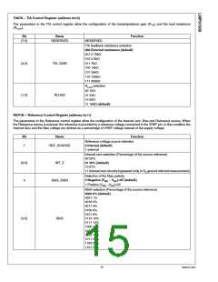
The Variable Bias block circuitry (Figure 2) provides the
amount of bias voltage required by a biased gas sensor be-
tween its reference and working electrodes. The bias voltage
can be programmed to be 1% to 24% (14 steps in total) of the
supply, or of the external reference voltage. The 14 steps can
be programmed through the I2C interface. The polarity of the
bias can be also programmed.
Transimpedance amplifier
Internal zero
The transimpedance amplifier (TIA in Figure 2) has 7 pro-
grammable internal gain resistors. This accommodates the
full scale ranges of most existing sensors. Moreover an ex-
ternal gain resistor can be connected to the LMP91000 be-
tween C1 and C2 pins. The gain is set through the I2C
interface.
The internal Zero is the voltage at the non-inverting pin of the
TIA. The internal zero can be programmed to be either 67%,
50% or 20%, of the supply, or the external reference voltage.
This provides both sufficient headroom for the counter elec-
trode of the sensor to swing, in case of sudden changes in the
gas concentration, and best use of the ADC’s full scale input
range.
11
www.ti.com

 TI [ TEXAS INSTRUMENTS ]