LM2900, LM3900
QUADRUPLE NORTON OPERATIONAL AMPLIFIERS
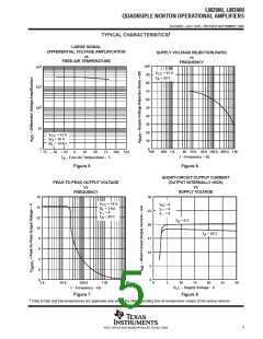
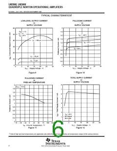
SLOS059 – JULY 1979 – REVISED SEPTEMBER 1990
APPLICATION INFORMATION
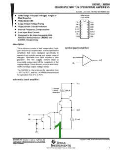
Norton (or current-differencing) amplifiers can be used in most standard general-purpose operational amplifier
applications. Performance as a dc amplifier in a single-power-supply mode is not as precise as a standard
integrated-circuit operational amplifier operating from dual supplies. Operation of the amplifier can best be
understood by noting that input currents are differenced at the inverting input terminal and this current then flows
through the external feedback resistor to produce the output voltage. Common-mode current biasing is generally
useful to allow operating with signal levels near (or even below) ground.
Internal transistors clamp negative input voltages at approximately –0.3 V but the magnitude of current flow has to
be limited by the external input network. For operation at high temperature, this limit should be approximately
–100 µA.
Noise immunity of a Norton amplifier is less than that of standard bipolar amplifiers. Circuit layout is more critical since
coupling from the output to the noninverting input can cause oscillations. Care must also be exercised when driving
either input from a low-impedance source. A limiting resistor should be placed in series with the input lead to limit the
peak input current. Current up to 20 mA will not damage the device, but the current mirror on the noninverting input
will saturate and cause a loss of mirror gain at higher current levels, especially at high operating temperatures.
V+
1 MΩ
10 kΩ
1 kΩ
1 MΩ
1 MΩ
–
+
Input
30 kΩ
100 kΩ
91 kΩ
Output
I
O
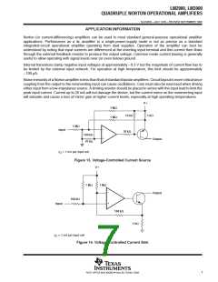
≈ 1 mA per input volt
Figure 13. Voltage-Controlled Current Source
V+
1 MΩ
1 MΩ
–
+
Output
100 kΩ
Input
100 kΩ
1 kΩ
I
O
≈ 1 mA per input volt
Figure 14. Voltage-Controlled Current Sink
7
POST OFFICE BOX 655303 • DALLAS, TEXAS 75265

 TI [ TEXAS INSTRUMENTS ]