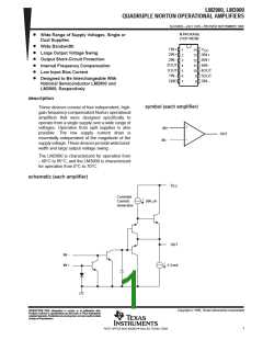
LM2900, LM3900
QUADRUPLE NORTON OPERATIONAL AMPLIFIERS
SLOS059 – JULY 1979 – REVISED SEPTEMBER 1990
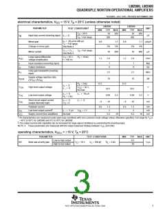
electrical characteristics, V
= 15 V, T = 25°C (unless otherwise noted)
CC
A
LM2900
TYP
30
LM3900
TYP
30
†
PARAMETER
TEST CONDITIONS
UNIT
MIN
MAX
MIN
MAX
T
= 25°C
200
200
A
I
IB
Input bias current (inverting input)
I
I
= 0
nA
I+
T
A
= Full range
300
300
= 20 µA to 200 µA
= Full range,
See Note 4
Mirror gain
I+
A
0.9
1.1
5%
0.9
1.1 µA/µA
T
Change in mirror gain
2%
10
2%
10
5%
V
= V
See Note 4
,
T = Full range,
A
I +
I –
Mirror current
500
500
µA
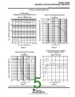
Large-signal differential
voltage amplification
V
= 10 V,
R
= 10 kΩ,
L
O
A
VD
1.2
2.8
1.2
2.8
V/mV
f = 100 Hz
r
r
Input resistance (inverting input)
Output resistance
1
8
1
8
MΩ
kΩ
i
o
Unity-gain bandwidth (inverting
input)
B
2.5
70
2.5
70
MHz
dB
1
Supply voltage rejection ratio
k
SVR
(∆V
CC
/∆V
IO)
R
V
= 2 kΩ
13.5
13.5
L
I
I
= 0,
= 0
I+
I –
V
V
High-level output voltage
V
= 30 V,
OH
CC
29.5
0.09
–18
29.5
0.09
–10
No load
I
R
= 0,
= 2 kΩ
I
I –
= 10 µA,
I+
Low-level output voltage
0.2
10
0.2
10
V
OL
L
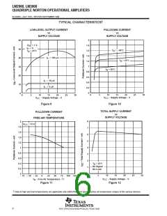
Short-circuit output current
(output internally high)
I
V
= 0,
= 0
I
I –
= 0,
I+
I
–6
–6
mA
OS
O
Pulldown current
0.5
1.3
5
0.5
1.3
5
mA
mA
mA
‡
I
I
Low-level output current
Supply current (four amplifiers)
I
I –
= 5 µA
V
OL
= 1 V
OL
No load
6.2
6.2
CC
†
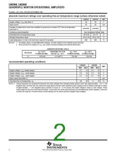
All characteristics are measured under open-loop conditions with zero common-mode voltage unless otherwise specified. Full range for T is
A
–40°C to 85°C for LM2900 and 0°C to 70°C for LM3900.
‡
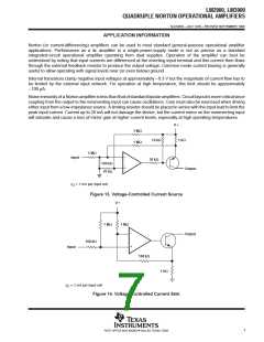
The output current-sink capability can be increased for large-signal conditions by overdriving the inverting input.
NOTE 4: These parameters are measured with the output balanced midway between V
CC
and GND.
operating characteristics, V
= ±15 V, T = 25°C
A
CC±
PARAMETER
TEST CONDITIONS
= 100 pF, R = 2 kΩ
L
MIN
TYP
0.5
20
MAX
UNIT
Low-to-high output
High-to-low output
SR
Slew rate at unity gain
V
O
= 10 V,
C
V/µs
L
3
POST OFFICE BOX 655303 • DALLAS, TEXAS 75265

 TI [ TEXAS INSTRUMENTS ]