LM2672
SNVS136K –SEPTEMBER 1998–REVISED APRIL 2013
www.ti.com
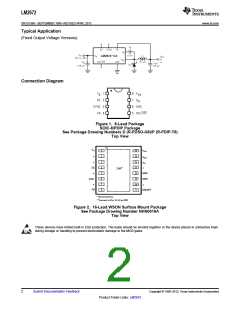
Typical Application
(Fixed Output Voltage Versions)
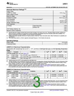
Connection Diagram
Figure 1. 8-Lead Package
SOIC-8/PDIP Package
See Package Drawing Numbers D (R-PDSO-G8)/P (R-PDIP-T8)
Top View
CB
1
2
3
16
15
14
13
12
11
10
9
VSW
VSW
VIN
*
*
SS
DAP**
4
5
6
7
8
*
GND
*
SYNC
GND
*
FB
*
ON/OFF
* No Connections
**Connect to Pins 11, 12 on PCB
Figure 2. 16-Lead WSON Surface Mount Package
See Package Drawing Number NHN0016A
Top View
These devices have limited built-in ESD protection. The leads should be shorted together or the device placed in conductive foam
during storage or handling to prevent electrostatic damage to the MOS gates.
2
Submit Documentation Feedback
Copyright © 1998–2013, Texas Instruments Incorporated
Product Folder Links: LM2672

 TI [ TEXAS INSTRUMENTS ]