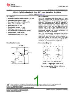
LF147, LF347-N
www.ti.com
SNOSBH1D –MAY 1999–REVISED MARCH 2013
DC Electrical Characteristics (1)(2) (continued)
Symbol
Parameter
Conditions
LF147
LF347B
LF347
Units
Min Typ Max Min Typ Max Min Typ Max
AVOL
Large Signal Voltage Gain VS=±15V, TA=25°C
VO=±10V, RL=2 kΩ
50 100
25
50
25
100
25
15
100
V/mV
Over Temperature
V/mV
V
VO
Output Voltage Swing
VS=±15V, RL=10 kΩ
±12 ±13.
5
±12 ±13.
5
±12 ±13.
5
VCM
Input Common-Mode
Voltage Range
±11 +15
−12
±11 +15
±11 +15
V
V
VS=±15V
−12
−12
CMRR Common-Mode Rejection RS≤10 kΩ
80 100
80
80
100
100
7.2
70
70
100
100
7.2
dB
Ratio
(4)
PSRR
IS
Supply Voltage Rejection See
Ratio
80 100
7.2
dB
Supply Current
11
11
11
mA
(4) Supply voltage rejection ratio is measured for both supply magnitudes increasing or decreasing simultaneously in accordance with
common practice from VS = ± 5V to ±15V for the LF347 and LF347B and from VS = ±20V to ±5V for the LF147.
(1)(2)
AC Electrical Characteristics
Symbol
Parameter
Conditions
LF147
LF347B
LF347
Units
Min Typ Max Min Typ Max Min Typ Max
Amplifier to Amplifier
Coupling
TA=25°C,
−120
−120
−120
dB
f=1 Hz−20 kHz
(Input Referred)
VS=±15V, TA=25°C
VS=±15V, TA=25°C
SR
Slew Rate
8
13
4
8
13
4
8
13
4
V/μs
MHz
GBW
en
Gain-Bandwidth Product
2.2
2.2
2.2
Equivalent Input Noise
Voltage
TA=25°C, RS=100Ω,
f=1000 Hz
20
20
20
nV / √Hz
in
Equivalent Input Noise
Current
Tj=25°C, f=1000 Hz
0.01
0.01
0.01
pA / √Hz
THD
Total Harmonic Distortion
AV=+10, RL=10k,
VO=20 Vp-p,
<0.0
2
<0.0
2
<0.0
2
%
BW=20 Hz−20 kHz
(1) Unless otherwise specified the specifications apply over the full temperature range and for VS=±20V for the LF147 and for VS=±15V for
the LF347B/LF347. VOS, IB, and IOS are measured at VCM=0.
(2) Refer to RETS147X for LF147D and LF147J military specifications.
Copyright © 1999–2013, Texas Instruments Incorporated
Submit Documentation Feedback
3
Product Folder Links: LF147 LF347-N

 TI [ TEXAS INSTRUMENTS ]