CC2510Fx / CC2511Fx
13.10.7 Clear Channel Assessment (CCA)
• Unless currently receiving a packet
The Clear Channel Assessment CCA) is used
to indicate if the current channel is free or
busy. The current CCA state is viewable on
• Both the above (RSSI below threshold
and not currently receiving a packet)
P1_5,
P1_6,
or
P1_7
by
setting
13.10.8 Link Quality Indicator (LQI)
IOCFGx.GDOx_CFG=1001.
The Link Quality Indicator is a metric of the
current quality of the received signal. If
PKTCTRL1.APPEND_STATUS is enabled, the
value is automatically added to the last byte
appended after the payload. The value can
also be read from the LQIstatus register. The
LQI gives an estimate of how easily a received
signal can be demodulated by accumulating
the magnitude of the error between ideal
constellations and the received signal over the
64 symbols immediately following the sync
MCSM1.CCA_MODE selects the mode to use
when determining CCA.
When the STXor SFSTXONcommand strobe is
given while CC2510Fx/CC2511Fx is in the RX
state, the TX or FSTXON state is only entered
if the clear channel requirements are fulfilled.
The chip will otherwise remain in RX (if the
channel becomes available, the radio will not
enter TX or FSTXON state before a new
strobe command is being issued). This feature
is called TX-if-CCA.
word. LQI is best used as
a
relative
measurement of the link quality (a high value
indicates a better link than what a low value
does), since the value is dependent on the
modulation format.
Four CCA requirements can be programmed:
• Always (CCA disabled, always goes to
TX)
• If RSSI is below threshold
13.11 Forward Error Correction with Interleaving
13.11.1 Forward Error Correction (FEC)
The
FEC
scheme
adopted
for
CC2510Fx/CC2511Fx is convolutional coding, in
which n bits are generated based on k input
bits and the m most recent input bits, forming
a code stream able to withstand a certain
number of bit errors between each coding
state (the m-bit window).
CC2510Fx/CC2511Fx has built in support for
Forward Error Correction (FEC). To enable
this option, set MDMCFG1.FEC_ENto 1. FEC is
only supported in fixed packet length mode
(PKTCTRL0.LENGTH_CONFIG=0). FEC is
employed on the data field and CRC word in
order to reduce the gross bit error rate when
The convolutional coder is a rate 1/2 code with
a constraint length of m=4. The coder codes
one input bit and produces two output bits;
hence, the effective data rate is halved. I.e. to
transmit at the same effective data rate when
using FEC, it is necessary to use twice as high
over-the-air data rate. This will require a higher
receiver bandwidth, and thus reduce
sensitivity. In other words, the improved
reception by using FEC and the degraded
sensitivity from a higher receiver bandwidth
will be counteracting factors.
operating
near
the
sensitivity
limit.
Redundancy is added to the transmitted data
in such a way that the receiver can restore the
original data in the presence of some bit
errors.
The use of FEC allows correct reception at a
lower SNR, thus extending communication
range. Alternatively, for a given SNR, using
FEC decreases the bit error rate (BER). As the
packet error rate (PER) is related to BER by:
PER = 1− (1− BER)packet _ length
,
13.11.2 Interleaving
a lower BER can be used to allow longer
packets, or a higher percentage of packets of
a given length, to be transmitted successfully.
Finally, in realistic ISM radio environments,
transient and time-varying phenomena will
produce occasional errors even in otherwise
good reception conditions. FEC will mask such
errors and, combined with interleaving of the
coded data, even correct relatively long
periods of faulty reception (burst errors).
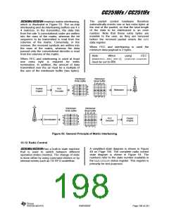
Data received through radio channels will
often experience burst errors due to
interference and time-varying signal strengths.
In order to increase the robustness to errors
spanning multiple bits, interleaving is used
when FEC is enabled. After de-interleaving, a
continuous span of errors in the received
stream will become single errors spread apart.
SWRS055F
Page 197 of 241

 TI [ TEXAS INSTRUMENTS ]