CC1110Fx / CC1111Fx
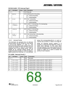
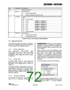
Bit
7:5
4
Field Name
Description
Reserved, write as 0
Boot Block Lock
BBLOCK
0
1
Page 0 is write protected
Page 0 is writeable, unless LSIZE is 000
3:1
LSIZE[2:0]
Lock Size. Sets the size of the upper flash area which is write-protected. Byte sizes are listed
below
000
001
010
011
100
101
110
111
32 KB (all pages)
24 KB
CC1110F32 and CC1111F32 only
CC1110F32 and CC1111F32 only
CC1110F32 and CC1111F32 only
CC1110F32 and CC1111F32 only
CC1110F32 and CC1111F32 only
CC1110F32 and CC1111F32 only
16 KB
8 KB
4 KB
2 KB
1 KB
0 bytes (no pages)
0
DBGLOCK
Debug lock bit
0
1
Disable debug commands
Enable debug commands
Table 44: Flash Lock Protection Bits Definition
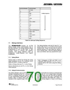
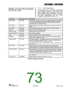
11.4 Debug Commands
The debug commands are shown in Table 45.
Some of the debug commands are described
in further detail in the following sections
CC1110Fx/CC1111Fx supports up to four hardware
breakpoints. When a hardware breakpoint is
enabled it will compare the CPU address bus
with the breakpoint. When a match occurs, the
CPU is halted.
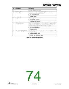
11.4.1
Debug Configuration
commands WR_CONFIG
When issuing the SET_HW_BRKPNT debug
command, the external host must supply three
data bytes that define the hardware
breakpoint. The hardware breakpoint itself
consists of 18 bits while three bits are used for
control purposes. The format of the three data
bytes for the SET_HW_BRKPNT command is
as follows.
The
and
RD_CONFIG are used to access the debug
configuration data byte. The format and
description of this configuration data is shown
in Table 46
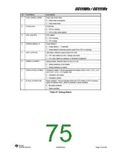
11.4.2
Debug Status
The first data byte consists of the following:
A debug status byte is read using the
READ_STATUS command. The format and
description of this debug status is shown in
Table 47.
Bit Description
7:5 Unused
The READ_STATUS command is used e.g.
for polling the status of flash chip erase after a
CHIP_ERASE command or oscillator stable
status required for debug commands HALT,
RESUME, DEBUG_INSTR, STEP_REPLACE,
and STEP_INSTR.
4:3 Breakpoint number; 0 - 3
2
Breakpoint enable
0
1
Disable
Enable
1:0 Reserved. Must be 00.
11.4.3
Hardware Breakpoints
The debug command SET_HW_BRKPNT is
used to set a hardware breakpoint. The
The second data byte consists of bits 15 - 8 of
the hardware breakpoint while the third data
byte consists of bits 7 - 0 of the hardware
SWRS033H
Page 72 of 246

 TI [ TEXAS INSTRUMENTS ]