CC1110Fx / CC1111Fx
13 Radio
RADIO CONTROL
ADC
LNA
ADC
RF_P
RF_N
FREQ
SYNTH
0
90
PA
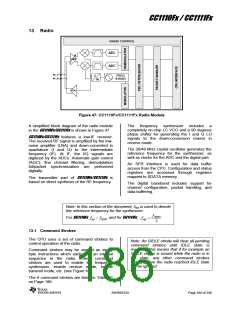
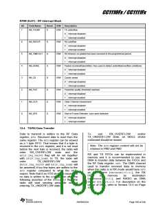
Figure 47: CC1110Fx/CC1111Fx Radio Module
A simplified block diagram of the radio module
The frequency synthesizer includes
a
completely on-chip LC VCO and a 90 degrees
phase shifter for generating the I and Q LO
signals to the down-conversion mixers in
receive mode.
in the CC1110Fx/CC1111Fx is shown in Figure 47.
CC1110Fx/CC1111Fx features a low-IF receiver.
The received RF signal is amplified by the low-
noise amplifier (LNA) and down-converted in
quadrature (I and Q) to the intermediate
frequency (IF). At IF, the I/Q signals are
digitized by the ADCs. Automatic gain control
(AGC), fine channel filtering, demodulation
bit/packet synchronization are performed
digitally.
The 26/48 MHz crystal oscillator generates the
reference frequency for the synthesizer, as
well as clocks for the ADC and the digital part.
An SFR interface is used for data buffer
access from the CPU. Configuration and status
registers are accessed through registers
mapped to XDATA memory.
The transmitter part of CC1110Fx/CC1111Fx is
based on direct synthesis of the RF frequency.
The digital baseband includes support for
channel configuration, packet handling, and
data buffering.
Note: In this section of the document, fRef is used to denote
the reference frequency for the synthesizer.
fXOSC
For CC1110Fx and for CC1111Fx,
fref fXOSC
fref
2
13.1 Command Strobes
The CPU uses a set of command strobes to
control operation of the radio.
Note: An SIDLE strobe will clear all pending
command strobes until IDLE state is
reached. This means that if for example an
SIDLE strobe is issued while the radio is in
RX state, any other command strobes
issued before the radio reached IDLE state
will be ignored.
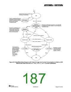
Command strobes may be viewed as single
byte instructions which each start an internal
sequence in the radio. These command
strobes are used to enable the frequency
synthesizer, enable receive mode, enable
transmit mode, etc. (see Figure 48).
The 6 command strobes are listed in Table 61
on Page 188.
SWRS033H
Page 186 of 246

 TI [ TEXAS INSTRUMENTS ]