bq24735
SLUSAK9 –SEPTEMBER 2011
www.ti.com
Setting the Charge Voltage
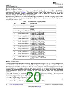
To set the output charge regulation voltage, write a 16bit ChargeVoltage() command (0x15H or 0b00010101)
using the data format listed in Table 5. The bq24735 provides charge voltage range from 1.024V to 19.200V,
with 16mV step resolution. Sending ChargeVoltage() below 1.024V or above 19.2V clears the register and
terminates charging. Upon POR, charge voltage limit is 0V.
The SRN pin is used to sense the battery voltage for voltage regulation and should be connected as close to the
battery as possible, and place a decoupling capacitor (0.1µF recommended) as close to the IC as possible to
decouple high frequency noise.
Table 5. Charge Voltage Register (0x15H)
BIT
0
BIT NAME
DESCRIPTION
Not used.
-
1
-
Not used.
2
-
Not used.
3
-
Not used.
4
Charge Voltage, DACV 0
0 = Adds 0mV of charger voltage.
1 = Adds 16mV of charger voltage.
5
6
Charge Voltage, DACV 1
Charge Voltage, DACV 2
Charge Voltage, DACV 3
Charge Voltage, DACV 4
Charge Voltage, DACV 5
Charge Voltage, DACV 6
Charge Voltage, DACV 7
Charge Voltage, DACV 8
Charge Voltage, DACV 9
Charge Voltage, DACV 10
-
0 = Adds 0mV of charger voltage.
1 = Adds 32mV of charger voltage.
0 = Adds 0mV of charger voltage.
1 = Adds 64mV of charger voltage.
7
0 = Adds 0mV of charger voltage.
1 = Adds 128mV of charger voltage.
8
0 = Adds 0mV of charger voltage.
1 = Adds 256mV of charger voltage.
9
0 = Adds 0mV of charger voltage.
1 = Adds 512mV of charger voltage.
10
11
12
13
14
15
0 = Adds 0mV of charger voltage.
1 = Adds 1024mV of charger voltage.
0 = Adds 0mV of charger voltage.
1 = Adds 2048mV of charger voltage.
0 = Adds 0mV of charger voltage.
1 = Adds 4096mV of charger voltage.
0 = Adds 0mV of charger voltage.
1 = Adds 8192mV of charger voltage.
0 = Adds 0mV of charger voltage.
1 = Adds 16384mV of charger voltage.
Not used.
Setting Input Current
System current normally fluctuates as portions of the system are powered up or put to sleep. With the input
current limit, the output current requirement of the AC wall adapter can be lowered, reducing system cost.
The total input current, from a wall cube or other DC source, is the sum of the system supply current and the
current required by the charger. When the input current exceeds the set input current limit, the bq24735
decreases the charge current to provide priority to system load current. As the system current rises, the available
charge current drops linearly to zero. Thereafter, all input current goes to system load and input current
increases.
During DPM regulation, the total input current is the sum of the device supply current IBIAS, the charger input
current, and the system load current ILOAD, and can be estimated as follows:
é
ê
ë
ù
ú
û
IBATTERY ´ VBATTERY
I
= ILOAD
+
+ IBIAS
INPUT
V
´ η
IN
(2)
where η is the efficiency of the charger buck converter (typically 85% to 95%).
20
Submit Documentation Feedback
Copyright © 2011, Texas Instruments Incorporated
Product Folder Link(s) :bq24735

 TI [ TEXAS INSTRUMENTS ]