bq20z80-V101
www.ti.com
SLUS625D–SEPTEMBER 2004–REVISED OCTOBER 2005
SIZE
(BYTES)
DEFAULT
VALUE
NAME
CLASS / SUBCLASS
FORMAT
VALID RANGE
UNITS
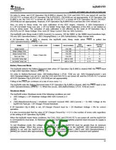
Shutdown Voltage
Shutdown Time
Charger Present
5000 to 20000
0 to 60
2
1
2
mV
s
7000
10
Power / Power (68)
Integer
0 to 23000
mV
16800
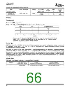
Display
Configuration
Number of LEDs Supported
DF:Operation Cfg A [LED1, LED0] determine the number of LEDs supported.
LED1
LED0
LEDs SUPPORTED
0
0
1
1
0
1
0
1
User(1)
3
4
5
(1) When User configuration selected, the LEDs are controlled as shown in the Display Format tables.
NOTE:
At power up, DF:Operation Cfg A [LED1, LED0] are read, the associated DSG Thresh
x and CHG Thresh x thresholds are set per the tables in the Display Format -
Discharge and Display Format - Charge sections.
Display Type
If DF:Operation Cfg A [SLED] = 0, then the LEDs are controlled as a parallel configuration display. However, if
DF:Operation Cfg A [SLED] = 1, then the LEDs are controlled as a series-configuration display and the
permanent failure display is disabled.
The serial LED option can be used to implement a much brighter display at the expense of additional hardware
components. With the normal connection, the 3.3 V output from the bq29312A is used to power the LEDs. Using
that approach, current in each LED should be limited to 3 mA maximum. With the serial option (DF:Operation Cfg
A [SLED] = 1), all LEDs can be powered from the battery voltage and driven in series through a simple constant
current regulator. The current is then diverted to ground at the various nodes between the series LEDs in order
to program the desired pattern.
Display Mode
The mode of the display is set in DF:Operation Cfg A [DMODE].
DMODE
LEDs SUPPORTED
Relative Mode (default)
Absolute Mode
% DATA
FULL REFERENCE
SBS.DesignCapacity( )
SBS.FullChargeCapacity( )
0
1
SBS.RelativeStateOfCharge( )
SBS.AbsoluteStateOfCharge( )
66

 TI [ TEXAS INSTRUMENTS ]