bq20z80-V101
www.ti.com
SLUS625D–SEPTEMBER 2004–REVISED OCTOBER 2005
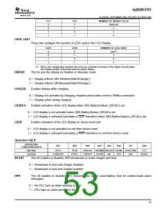
CC1
CC0
NUMBER OF SERIES CELLS
0
0
1
1
0
1
0
1
Reserved
2
3
4
LED0, LED1
These bits configure the number of LEDs used in the LED Display.
LED1
LED0
NUMBER OF LEDs USED
0
0
1
1
0
1
0
1
User(1)
3
4
5
(1) When User configuration selected, the LEDs are controlled as shown in the Display Format tables.
See Display section of this data sheet for further details.
DMODE
This bit sets the display as Relative or Absolute mode.
0 = Display reflects SBS.RelativeStateOfCharge( )
1 = Display reflects SBSAbsoluteStateOfCharge( )
CHGLED
LEDRCA
LEDR
Enables display while charging.
0 = Display not activated by charging, requires push-button event or SMBus command.
1 = Display active during charging.
Enables activation of the LED display when SBS.BatteryStatus( ) [RCA] is set.
0 = LED display is not activated when SBS.BatteryStatus( ) [RCA] is set.
1 = LED display is activated (simulates a DISP transition) when SBS.BatteryStatus( ) [RCA] is set.
Enables activation of the LED display on device-reset exit.
0 = LED display is not activated on exit from device reset.
1 = LED display is activated (simulates a DISP transition) on exit from device reset.
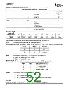
Operation Cfg B
OPERATION
CONFIGURATION B
bit7
bit6
bit5
bit4
bit3
bit2
bi1
bit0
High Byte
Low Byte
PFD1
PFD0
RESCAP
CHGFET
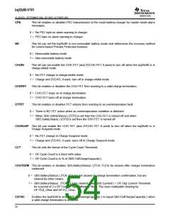
NCSMB NRCHG CSYNC CHGTERM
CHGIN NR CPE HPE
CCT
CHGSUSP
OTFET
BCAST
BCAST
HPE
This bit enables or disables SBS broadcasts to smart charger and host.
0 = Broadcasts to host and charger disabled
1 = Broadcasts to host and charger enabled
This bit enables or disables PEC transmissions to the smart-battery host for master-mode alarm
messages.
0 = No PEC byte on alarm warning to host
1 = PEC byte on alarm warning to host
53

 TI [ TEXAS INSTRUMENTS ]