bq20z80-V101
www.ti.com
SLUS625D–SEPTEMBER 2004–REVISED OCTOBER 2005
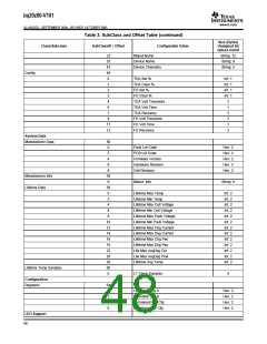
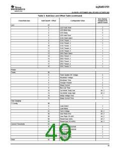
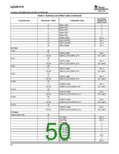
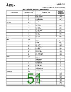
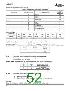
Table 3. SubClass and Offset Table (continued)
Size (Bytes)
Unsigned Int
unless noted
Class/Subclass
SubClassID / Offset
Configurable Value
16
18
20
22
107
0
Int Coef 3
Int: 2
Int: 2
Int: 2
Int: 2
Int Coef 4
Int Min AD
Int Max Temp
Current
Filter
1
1
1
1
2
2
1
Deadband
CC Deadband
2
3
CC Max Deadband
4
CC Deadband Sample
CC Max Offset Sample
6
Operation Cfg A
OPERATION
CONFIGURATION A
bit7
bit6
bit5
bit4
bit3
bit2
bi1
bit0
High Byte
Low Byte
LEDR
RSVD
LEDRCA
RSVD
CHGLED
SLEEP
DMODE
TEMP1
LED1
LED0
SLED
CC1
CC0
TEMP0
ZVCHG1
ZVCHG0
The Operation Cfg bits enable, disable, and configure various features of the bq20z80.
RSVD These bits are reserved and MUST be programmed to 0.
ZVCHG0, ZVCHG1 These bits enable or disable the use of ZVCHG or CHG FET for Zero-Volt/Precharge modes.
ZVCHG1
ZVCHG0
FET USED
ZVCHG
CHG
0
0
1
1
0
1
0
1
OD
No Action
SLED
Enables the bq20z80 display to be used in serial or parallel mode.
0 = Display is in parallel LED mode (default)
1 = Display is in serial LED mode
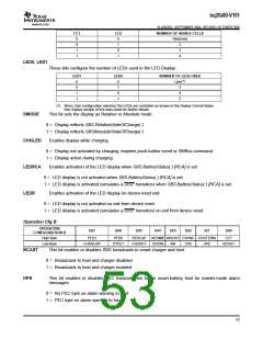
TEMP0, TEMP1 These bits select the measurement source used for SBS.Temperature( ).
TEMP1
TEMP0
TEMPERATURE() SOURCE
Internal Temperature Sensor
TS1 Input (default)
0
0
1
1
0
1
0
1
Maximum of TS1 or TS2 Inputs
Average of TS1 and TS2 Inputs
SLEEP
Enables the bq20z80 to enter Sleep mode.
0 =
1 =
bq20z80 never enters Sleep
bq20z80 enters Sleep mode under normal Sleep entry requirements
CC0, CC1
These bits configure the bq20z80 for the number of series cells in the battery stack.
52

 TI [ TEXAS INSTRUMENTS ]