ꢀ ꢁ ꢂꢃ ꢄꢅꢆ ꢂ ꢇ ꢈ ꢀ ꢁ ꢂꢃ ꢄꢅ ꢆ ꢂꢉ
ꢄ ꢊꢋꢌꢅ ꢊꢄꢍꢀ ꢎꢏ ꢐꢉ ꢎ ꢐꢌꢑ ꢒꢏ ꢏ ꢓ ꢔ ꢕꢀꢓ ꢖꢕ ꢒꢄ ꢏ ꢓꢉ ꢗꢗ ꢏꢖ ꢏꢘꢍ ꢉꢀ ꢄ ꢄ ꢉꢘꢏ ꢖꢏꢇ ꢏꢉꢅ ꢏꢖ
SLLS202E − MAY 1995 − REVISED JUNE 2005
APPLICATION INFORMATION
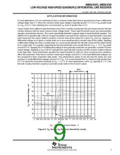
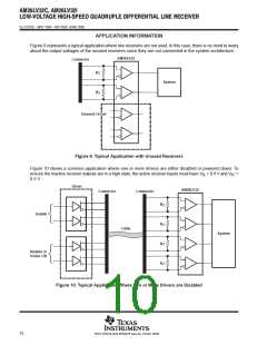
Figure 9 represents a typical application where two receivers are not used. In this case, there is no need to worry
about the output voltages of the unused receivers since they are not connected in the system architecture.
AM26LV32
Connector
R
R
T
T
System
Unused Circuit
Figure 9. Typical Application with Unused Receivers
Figure 10 shows a common application where one or more drivers are either disabled or powered down. To
ensure the inactive receiver outputs are in a high state, the active receiver inputs must have V > 0.4 V and V
0.5 V.
>
IL
IC
Driver
AM26LV32
Connector
Connector
R
R
R
R
T
T
T
T
Enable
Cable
System
Disable or
Power Off
Figure 10. Typical Application Where Two or More Drivers are Disabled
10
POST OFFICE BOX 655303 • DALLAS, TEXAS 75265

 TI [ TEXAS INSTRUMENTS ]