71M6515H
Energy Meter IC
DATA SHEET
MARCH 2008
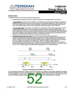
read
read
commands
fromhost
commands
fromhost
6515Hnot
ready
6515Hnot
ready
6515Hdata
6515Hdata
post-processor
active
post-processor
active
time
330ms
330ms
1000ms
2000ms
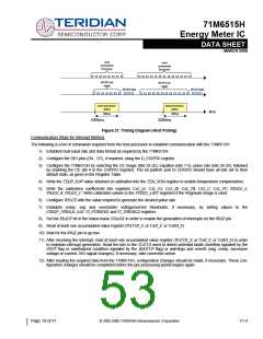
Figure 21: Timing Diagram (Host Polling)
Communication Steps for Interrupt Method:
The following is a list of commands required from the host processor to establish communication with the 71M6515H.
1) Establish host baud rate and data format as required by the 71M6515H.
2) Configure the DIO pins (D0…D7), if required, using the D_CONFIG register
3) Configure the 71M6515H by selecting the CE image (bits 23-22), equation (bits 7-5), pulse rate (bits 26-25), followed
by enabling the CE (bit 4 in the CONFIG register). The bit pattern sent to CONFIG should have all bits set to their
default state, as given in the Register Table.
4) Write the TEMP_RAW value obtained at calibration into the TEM_NOM register to enable temperature compensation.
5) Write the calibration coefficients into registers CAL_IA, CAL_VA, CAL_IB, CAL_VB, CAL_C, CAL_VC, PHADJ_A,
PHADJ_B, PHADJ_C. Write calibration values to the VFEED_A/B/C registers if the Rogowski image is used.
6) Configure WRATE with the value required to generate the desired pulse rate.
7) Establish creep, sag and over/under voltage/current thresholds, if necessary, by writing values to the
CREEP_THRSLD, SAG, VI_PTHRESH, and VI_THRSHLD registers.
8) Set the READY bit in the status mask STMASK in order to enable the generation of interrupts on the IRQZ pin.
9) Read at least one accumulated value register (WATTH_X, or VAH_X, or VARH_X).
10) Wait for the IRQZ pin to go low.
11) After receiving the interrupt, read at least one accumulated value register (WATTH_X, or VAH_X, or VARH_X) in order
to maintain interrupt generation. Read the bits in the STATUS word to detect potential faults (overflow signaled by the
XOVF flag or uninitialized condition signaled by the BOOTUP flag) or warnings and events (sag, creep, excessive
voltage or current, DIO signal changes). If necessary, take corrective action.
12) After reading the required data from the 71M6515H, configuration changes should be made, if necessary. These con-
figuration changes should be completed before the pre-processing period begins again.
Page: 53 of 57
© 2005-2008 TERIDIAN Semiconductor Corporation
V1.4

 TERIDIAN [ TERIDIAN SEMICONDUCTOR CORPORATION ]