Data Sheets
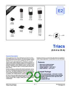
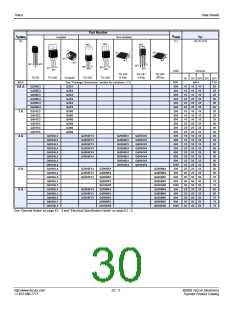
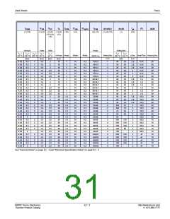
Triacs
2
V
(1) (5)
V
I
I
P
(14)
P
I
TSM
(9) (13)
tgt
(10) (17)
dv/dt(c)
(1) (4) (13)
dv/dt
(1)
I t
di/dt
TM
GT
H
GTM
GM
G(AV)
(2) (6) (15) (1) (8) (12)
(14)
(18) (19)
Volts
Volts
Amps
Volts/µSec
TC
100 °C
MIN
150
150
100
75
=
TC =
mAmps
Amps
Watts
Watts
Volts/µSec
µSec
Amps2Sec Amps/µSec
T
C = 25 °C TC = 25 °C
60/50 Hz
125 °C
MAX
1.6
1.6
1.6
1.6
1.6
1.6
1.6
1.6
1.6
1.6
1.6
1.6
1.6
1.6
1.6
1.8
1.8
1.8
1.8
1.8
1.4
1.4
1.5
1.5
MAX
2.5
2.5
2.5
2.5
2.5
2.5
2.5
2.5
2.5
2.5
2.5
2.5
2.5
2.5
2.5
2.5
2.5
2.5
2.5
2.5
2.75
2.75
2.75
2.75
MAX
35
35
35
35
35
50
50
50
50
50
70
70
70
70
70
100
100
100
100
100
50
50
50
50
TYP
2
2
2
2
2
4
4
4
4
4
4
4
4
4
4
5
5
5
5
5
5
5
5
5
TYP
3
3
3
3
3
3
3
3
3
3
4
4
4
4
4
4
4
4
4
4
3
3
3
3
1.8
1.8
1.8
1.8
1.8
1.8
1.8
1.8
1.8
1.8
2
2
2
2
2
2
2
2
2
20
20
20
20
20
20
20
20
20
20
20
20
20
20
20
20
20
20
20
20
20
20
20
20
0.5
0.5
0.5
0.5
0.5
0.5
0.5
0.5
0.5
0.5
0.5
0.5
0.5
0.5
0.5
0.5
0.5
0.5
0.5
0.5
0.5
0.5
0.5
0.5
120/100
120/100
120/100
120/100
120/100
120/100
120/100
120/100
120/100
120/100
200/167
200/167
200/167
200/167
200/167
200/167
200/167
200/167
200/167
200/167
250/220
250/220
350/300
350/300
60
60
60
70
70
70
60
60
70
70
50
350
350
300
250
150
400
400
350
300
200
400
400
350
300
200
550
450
550
450
225
225
200
175
60
60
70
70
60
60
70
70
60
70
275
275
225
200
166
166
166
166
166
166
166
166
166
166
260
260
508
508
100
100
100
100
100
100
100
100
100
100
100
100
100
100
275
275
225
200
2
2
2
2
475
400
475
400
2
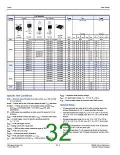
(15) RL = 60 Ω for 0.8 A to10 A triacs; RL = 30 Ω for 15 A to 35 A triacs
(16) TC = TJ for test conditions in off state
(17) IGT = 300 mA for 25 A and 35 A devices
(18) Quadrants I, II, III only
(19) Minimum non-trigger VGT at 125 °C is 0.2 V for all except 50 mA
MAX QIV devices which are 0.2 V at 110 °C.
Electrical Specification Notes
(1) For either polarity of MT2 with reference to MT1 terminal
(2) For either polarity of gate voltage (VGT) with reference to MT1
terminal
(3) See Gate Characteristics and Definition of Quadrants.
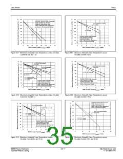
(4) See Figure E2.1 through Figure E2.7 for current rating at specific
operating temperature.
Gate Characteristics
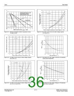
(5) See Figure E2.8 through Figure E2.10 for iT versus vT
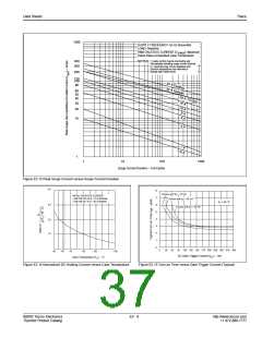
(6) See Figure E2.12 for VGT versus TC.
(7) See Figure E2.11 for IGT versus TC.
.
Teccor triacs may be turned on between gate and MT1 terminals
in the following ways:
•
•
In-phase signals (with standard AC line) using Quadrants I
and III
Application of unipolar pulses (gate always positive or nega-
tive), using Quadrants II and III with negative gate pulses and
Quadrants I and IV with positive gate pulses
(8) See Figure E2.14 for IH versus TC.
(9) See Figure E2.13 for surge rating with specific durations.
(10) See Figure E2.15 for tgt versus IGT
.
(11) See package outlines for lead form configurations. When ordering
special lead forming, add type number as suffix to part number.
However, due to higher gate requirements for Quadrant IV, it
is recommended that only negative pulses be applied. If pos-
itive pulses are required, see “Sensitive Triacs” section of
this catalog or contact the factory. Also, see
(12) Initial on-state current = 200 mA dc for 0.8 A to10 A devices,
400 mA dc for 15 A to 35 A devices
(13) See Figure E2.1 through Figure E2.6 for maximum allowable case
temperature at maximum rated current.
Figure AN1002.8, “Amplified Gate” Thyristor Circuit.
(14) Pulse width ≤10 µs; IGT ≤ IGTM
©2002 Teccor Electronics
Thyristor Product Catalog
E2 - 5
http://www.teccor.com
+1 972-580-7777

 TECCOR [ TECCOR ELECTRONICS ]