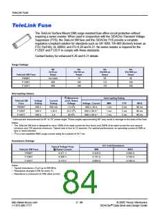
TeleLink Fuse
Qualification Data
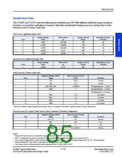
The F1250T and F1251T meet the following test conditions per GR 1089 without additional series resistance.
However, in-circuit test verification is required. Note that considerable heating may occur during Test 4 of the
Second Level AC Power Fault Test.
First Level Lightning Surge Test
Surge Voltage
Wave-form
µs
Surge Current
Amps
Repetitions Each
Polarity
Test
Volts
1
2
3
4
5
±600
±1000
±1000
±2500
±1000
10x1000
10x360
10x1000
2x10
100
100
100
500
25
25
25
25
10
5
10x360
Second Level Lightning Surge Test
Surge Voltage
Wave-form
µs
Surge Current
Amps
Repetitions Each
Polarity
Test
Volts
1
±5000
2x10
500
1
First Level AC Power Fault Test
Applied Voltage, 60 Hz
VRMS
Short Circuit Current
Test
1
Amps
Duration
15 min
50
0.33
2
100
0.17
15 min
3
4
5
6
7
8
9
200, 400, 600
1 at 600 V
60 applications, 1 s each
60 applications, 1 s each
60 applications, 5 s each
30 s each
1000
*
600
600
600
1000
1
*
0.5
2.2
3
2 s each
1 s each
0.5 s each
5
* Test 5 simulates a high impedance induction fault. For specific information, please contact Teccor Electronics.
Second Level AC Power Fault Test for Non-Customer Premises Equipment
Applied Voltage, 60 Hz
Short Circuit Current
Test
VRMS
Amps
Duration
30 min
5 s
5 s
30 min
1
2
3
4
120, 277
600
600
30
60
7
100-600
2.2 at 600 V
Notes:
•
•
•
Power fault tests equal or exceed the requirements of UL 60950 3rd edition.
Test 4 is intended to produce a maximum heating effect. Temperature readings can exceed 150 °C.
Test 2 may be dependent on the closing angle of the voltage source. Fuse is characterized at 50° to 70°. Closing angles
approximating 90° may result in damage to the body of the fuse.
Use caution when routing internal traces adjacent to the F1250T and F1251T.
•
© 2002 Teccor Electronics
2 - 67
http://www.teccor.com
+1 972-580-7777
®
SIDACtor Data Book and Design Guide

 TECCOR [ TECCOR ELECTRONICS ]