Data Sheets
Sensitive Triacs
2
V
V
I
I
P
P
I
t
dv/dt(c)
dv/dt
I t
di/dt
TM
(1) (4)
GT
(2) (5) (15)
H
GTM
(13)
GM
(13)
G(AV)
TSM
(8) (10)
gt
(9)
(1) (7)
(1) (10)
(1)
Volts
Volts
Amps
60/50 Hz
Volts/µSec
TC = 100 °C
mAmps
Amps
Watts
Watts
Volts/µSec
µSec
Amps2Sec
Amps/µSec
T
C = 25 °C TC = 25 °C
MAX
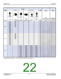
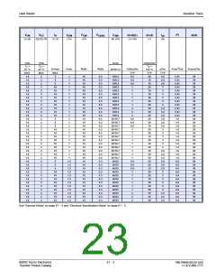
1.6
1.6
1.6
1.6
1.6
1.6
1.6
1.6
1.6
1.6
1.6
1.6
1.6
1.6
1.6
MAX
2
MAX
10
10
10
10
10
10
20
20
20
10
10
10
20
20
20
TYP
1
TYP
40
30
20
40
30
20
45
40
30
40
30
20
45
40
30
TYP
3
1.6
1.6
1.6
1.6
1.6
1.6
1.6
1.6
1.6
1.6
1.6
1.6
1.6
1.6
1.6
18
18
18
18
18
18
18
18
18
18
18
18
18
18
18
0.4
0.4
0.4
0.4
0.4
0.4
0.4
0.4
0.4
0.4
0.4
0.4
0.4
0.4
0.4
60/50
60/50
60/50
60/50
60/50
60/50
60/50
60/50
60/50
80/65
80/65
80/65
80/65
80/65
80/65
15
15
70
70
70
70
70
70
70
70
70
70
70
70
70
70
70
2
1
3
2
1
3
15
2
2
3
15
2
2
3
15
2
2
3
15
2
2
3.2
3.2
3.2
3
15
2
2
15
2
2
15
2
2
26.5
26.5
26.5
26.5
26.5
26.5
2
2
3
3
3.2
3.2
3.2
2
2
2
2
2
2
2
2
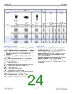
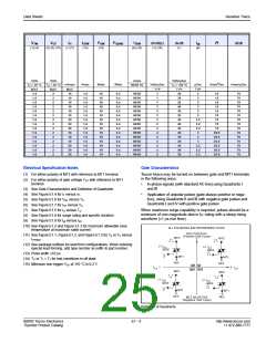
Electrical Specification Notes
Gate Characteristics
(1) For either polarity of MT2 with reference to MT1 terminal
Teccor triacs may be turned on between gate and MT1 terminals
in the following ways:
(2) For either polarity of gate voltage VGT with reference to MT1
terminal
•
•
In-phase signals (with standard AC line) using Quadrants I
and III
Application of unipolar pulses (gate always positive or nega-
tive), using Quadrants II and III with negative gate pulses and
Quadrants I and IV with positive gate pulses
(3) See Gate Characteristics and Definition of Quadrants.
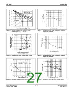
(4) See Figure E1.4 for iT versus vT.
(5) See Figure E1.6 for VGT versus TC.
(6) See Figure E1.7 for IGT versus TC.
(7) See Figure E1.5 for IH versus TC.
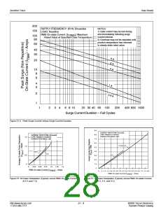
(8) See Figure E1.9 for surge rating and specific duration.
When maximum surge capability is required, pulses should be a
minimum of one magnitude above IGT rating with a steep rising
waveform (≤1 µs rise time).
(9) See Figure E1.8 for tgt versus IGT
.
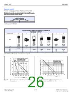
(10) See Figure E1.2 and Figure E1.3 for maximum allowable case
ALL POLARITIES ARE REFERENCED TO MT1
temperature at maximum rated current.
MT2 POSITIVE
(11) See Figure E1.1, Figure E1.2, and Figure E1.3 for TA or TC versus
(Positive Half Cycle)
MT2
MT2
+
IT(RMS)
.
(12) See package outlines for lead form configurations. When ordering
(-)
I
GATE
(+)
I
GT
GT
special lead forming, add type number as suffix to part number.
GATE
(13) Pulse width ≤10 µs
(14) TC or TL = TJ for test conditions in off state
(15) Minimum non-trigger VGT at 110 °C is 0.2 V.
MT1
MT1
REF
MT2
REF
MT2
QII QI
QIII QIV
I
-
+ I
GT
GT
(-)
I
GATE
(+)
I
GATE
GT
GT
MT1
REF
MT1
REF
-
MT2 NEGATIVE
(Negative Half Cycle)
Definition of Quadrants
©2002 Teccor Electronics
Thyristor Product Catalog
E1 - 5
http://www.teccor.com
+1 972-580-7777

 TECCOR [ TECCOR ELECTRONICS ]