(4/9)
Conformity to RoHS Directive
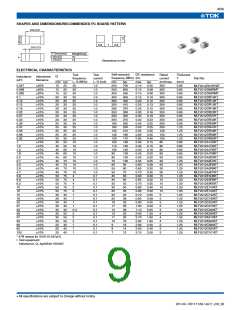
Inductors for Standard Circuits
Multilayer/STD • Magnetic Shielded
MLF Series MLF1608
FEATURES
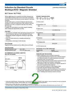
PRODUCT IDENTIFICATION
MLF 1608 1R0
(1) (2) (3) (4) (5) (6)
• High-reliability monolithic structure.
• Ferrite core and magnetic shielding enables the design of com-
pact circuits with high density mounting.
• Excellent solderability and high heat resistance permits either
flow or reflow soldering.
A
K
T
(7)
(1) Series name
(2) Dimensions L×W
• The products contain no lead and also support lead-free
soldering.
1608
1.6×0.8mm
• It is a product conforming to RoHS directive.
(3) Type name
(4) Inductance
APPLICATIONS
Digital cellular phone, tuner, personal computers, audio, or various
electronic appliances
47N
R15
1R0
47nH[0.047µH]
0.15µH
1µH
SPECIFICATIONS
Operating temperature range
Storage temperature range
–40 to +85°C
–40 to +85°C(After mount)
(5) Tolerance
K
M
10%
20%
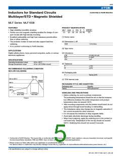
RECOMMENDED SOLDERING CONDITION
REFLOW SOLDERING
(6) Packaging style
T
Taping [reel]
10s max.
250 to 260˚C
230˚C
(7) TDK internal code
Natural
cooling
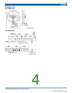
PACKAGING STYLE AND QUANTITIES
Packaging style
Taping
Quantity
4000 pieces/reel
180˚C
150˚C
Preheating
60 to 120s
Soldering
30 to 60s
HANDLING AND PRECAUTIONS
• Before soldering, be sure to preheat components.
The preheating temperature should be set so that the tempera-
ture difference between the solder temperature and product
temperature does not exceed 150°C.
Time(s)
• After mounting components onto the printed circuit board, do not
apply stress through board bending or mishandling.
• The inductance value may change due to magnetic saturation if
the current exceeds the rated maximum.
• Do not expose the inductors to stray magnetic fields.
• Avoid static electricity discharge during handling.
• When hand soldering, apply the soldering iron to the printed cir-
cuit board only. Temperature of the iron tip should not exceed
350°C. Soldering time should not exceed 3 seconds.
• Conformity to RoHS Directive: This means that, in conformity with EU Directive 2002/95/EC, lead, cadmium, mercury, hexavalent chromium, and specific
bromine-based flame retardants, PBB and PBDE, have not been used, except for exempted applications.
• Please contact our Sales office when your application is considered the following:
The device’s failure or malfunction may directly endanger human life (e.g. application for automobile/aircraft/medical/nuclear power devices, etc.)
• All specifications are subject to change without notice.
001-05 / 20111129 / e511_mlf_02

 TDK [ TDK ELECTRONICS ]