ICM-20690
10.5 ACCELEROMETER LOW-POWER MODE
Changing the value of SMPLRT_DIV register in Accelerometer Low-Power mode will take effect after up to one sample at the old
ODR.
10.6 SENSOR MODE CHANGE
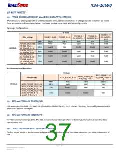
When switching from low-power modes to low-noise modes, unsettled output samples may be observed at the gyroscope or
accelerometer outputs due to filter switching and settling. The number of unsettled output samples depends on the filter and ODR
settings. The number of unsettled output samples is minimized by selecting the widest low-noise-mode filter bandwidth consistent
with the chosen ODR.
10.7 TEMP SENSOR DURING GYROSCOPE STANDBY MODE
During transition from Gyro Low power mode (GYRO_CYCLE=1), to Gyro Standby mode, in addition to the Gyro axis (axes) being
turned off, the Temp Sensor will also be turned off if the Accel is disabled. In order to keep the temp sensor on during Gyroscope
standby mode when Accel is disabled, the following procedure should be followed:
Set GYRO_CYCLE = 0 at least one ODR cycle prior to entering Standby mode
At least one of the Gyro axis is ON prior to entering Standby mode
Set GYRO_STANDBY = 1
10.8 GYROSCOPE MODE CHANGE
Gyroscope will take one ODR clock period to switch from Low-Noise to Low-Power mode after GYRO_CYCLE bit is set.
If GYRO_CYCLE is set to 1 prior to turning on the gyroscope, the first sample will be from low-noise mode, which may not be a
settled value. It is therefore recommended to ignore the first reading in this case.
10.9 POWER MANAGEMENT 1 REGISTER SETTING
It is required to set CLKSEL[2:0] to 001 (auto-select) for full performance.
10.10 UNLISTED REGISTER LOCATIONS
Do not read unlisted register locations in Sleep mode as this may cause the device to hang up, requiring power cycle to restore
operation.
10.11 CLOCK TRANSITION WHEN GYROSCOPE IS TURNED OFF
When the gyroscope is on, the on-chip master clock source will be the gyroscope clock (assuming CLKSEL[2:0] = 001 for auto-select
mode); otherwise, the master clock source will be the internal oscillator as long as the part is not in Sleep mode. During a power
mode transition, whenever the gyroscope is disabled and the part enters a mode other than Sleep, the on-chip master clock source
will transition from the gyroscope clock to the internal oscillator. It will take about 20 ms for this transition to complete.
10.12 SLEEP MODE
The part will only enter Sleep mode when the SLEEP bit in PWR_MGMT_2 is set to ‘1’. If SLEEP bit is ‘0’ and bit STBY_[X,Y,Z]A and
STBY_[X,Y,Z]G are all set to ‘1’, accelerometer and gyroscope will be turned off, but the on-chip master clock will still be running and
consuming power.
10.13 NO SPECIAL OPERATION NEEDED FOR FIFO READ IN LOW POWER MODE
The use of FIFO is enabled in all modes including low power mode.
Page 38 of 76
Document Number: DS-000178
Revision: 1.0

 TDK [ TDK ELECTRONICS ]