C2510Fx / CC2511Fx
14.17 System considerations and Guidelines
14.17.1 SRD Regulations
The VCO current calibration result is available
in FSCAL2 and is not dependent on the RF
frequency. Neither is the charge pump current
calibration result available in FSCAL3. The
same value can therefore be used for all
frequencies.
International regulations and national laws
regulate the use of radio receivers and
transmitters. The most important regulations
for the 2.4 GHz band are EN 300 440 and EN
300 328 (Europe), FCC CFR47 part 15.247
and 15.249 (USA), and ARIB STD-T66
(Japan). A summary of the most important
aspects of these regulations can be found in
Application Note AN032 [9].
3) Run calibration on a single frequency at
startup. Next write 0 to FSCAL3[5:4] to
disable the charge pump calibration. After
writing to FSCAL3[5:4] strobe SRX (or STX)
with MCSM0.FS_AUTOCAL=1 for each new
frequency hop. That is, VCO current and VCO
capacitance calibration is done but not charge
pump current calibration. When charge pump
current calibration is disabled the calibration
time is reduced from approximately 720 µs to
approximately 150 µs when fRef is 26 MHz and
from 780 µs to 163 µs when fRef is 24 MHz.
The blanking interval between each frequency
hop is then approximately 240 µs us and 260
µs respectively.
Please note that compliance with regulations is
dependent on complete system performance.
It is the customer’s responsibility to ensure that
the system complies with regulations.
14.17.2
Frequency Hopping and Multi-
Channel Systems
The 2.400 – 2.4835 GHz band is shared by
many systems both in industrial, office and
home
environments.
It
is
therefore
recommended to use frequency hopping
spread spectrum (FHSS) or a multi-channel
protocol because the frequency diversity
makes the system more robust with respect to
interference from other systems operating in
the same frequency band. FHSS also combats
multipath fading.
There is a trade off between blanking time and
memory space needed for storing calibration
data in non-volatile memory. Solution 2) above
gives the shortest blanking interval, but
requires more memory space to store
calibration
values.
Solution
3)
gives
approximately 570 µs smaller blanking interval
than solution 1 when fRef is 24 MHz and
approximately 615 µs smaller blanking interval
than solution 1 when fRef is 24 MHz ).
Charge pump current, VCO current and VCO
capacitance array calibration data is required
for each frequency when implementing
frequency hopping for CC2510Fx/CC2511Fx.
There are 3 ways of obtaining the calibration
data from the chip:
14.17.3
Wideband Modulation not Using
Spread Spectrum
1) Frequency hopping with calibration for each
hop. The PLL calibration time is approximately
720 µs and the blanking interval between each
frequency hop is then approximately 810 µs
(PLL turn on time is 90 us) when fRef is 26
MHz. When fRef is 24 MHz, these numbers are
780 µs and 875 µs respectively.
Digital modulation systems under FCC part
15.247 includes 2-FSK and GFSK modulation.
A maximum peak output power of 1 W (+30
dBm) is allowed if the 6 dB bandwidth of the
modulated signal exceeds 500 kHz. In
addition, the peak power spectral density
conducted to the antenna shall not be greater
than +8 dBm in any 3 kHz band.
2) Fast frequency hopping without calibration
for each hop can be done by calibrating each
frequency at startup and saving the resulting
FSCAL3, FSCAL2 and FSCAL1 register values
in memory. Between each frequency hop, the
calibration process can then be replaced by
writing the FSCAL3, FSCAL2 and FSCAL1
register values corresponding to the next RF
frequency. The PLL turn on time is
approximately 90 µs when fRef is 26 MHz and
95 µs when fRef is 24 MHz. The blanking
interval between each frequency hop is then
approximately equal to the PLL turn on time.
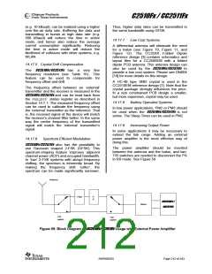
Operating at high data rates and high
frequency separation, the CC2510Fx/CC2511Fx is
suited for systems targeting compliance with
digital modulation systems as defined by FCC
part 15.247. An external power amplifier is
needed to increase the output above +1 dBm.
14.17.4
Data Burst Transmissions
high maximum data
The
rate
of
CC2510Fx/CC2511Fx opens up for burst
transmissions. A low average data rate link
SWRS055D
Page 211 of 243

 TAOS [ TEXAS ADVANCED OPTOELECTRONIC SOLUTIONS ]