C2510Fx / CC2511Fx
The base or start frequency is set by the 24 bit
frequency word located in the FREQ2, FREQ1
and FREQ0 registers. This word will typically
be set to the centre of the lowest channel
frequency that is to be used.
The desired channel number is programmed
with the 8-bit channel number register,
CHANNR.CHAN, which is multiplied by the
channel offset. The resultant carrier frequency
is given by:
fref
216
fcarrier
=
⋅
(
FREQ + CHAN ⋅
(
(256 + CHANSPC _ M ) ⋅ 2CHANSPC _ E−2 ))
With a reference frequency, fRef, equal to 26
MHz, the maximum channel spacing is 405
kHz. To get e.g. 1 MHz channel spacing one
solution is to use 333 kHz channel spacing
Note that the SmartRF® Studio software [8]
automatically calculates the optimum register
setting based on channel spacing and channel
filter bandwidth.
and
select
each
third
channel
in
If any frequency programming register is
altered when the frequency synthesizer is
running, the synthesizer may give an
undesired response. Hence, the frequency
programming should only be updated when
the radio is in the IDLE state.
CHANNR.CHAN.
The preferred IF frequency is programmed
with the FSCTRL1.FREQ_IF register. The IF
frequency is given by:
fref
fIF
=
⋅ FREQ _ IF
210
14.14 VCO
The VCO is completely integrated on-chip.
14.14.1 VCO and PLL Self-Calibration
The calibration can be initiated automatically or
manually.
The
synthesizer
can
be
automatically calibrated each time the
synthesizer is turned on, or each time the
synthesizer is turned off automatically. This is
configured with the MCSM0.FS_AUTOCAL
register setting. In manual mode, the
calibration is initiated when the SCAL
command strobe is activated in the IDLE
mode.
The VCO characteristics will vary with
temperature and supply voltage changes, as
well as the desired operating frequency. In
order
to
ensure
reliable
operation,
CC2510Fx/CC2511Fx
includes
frequency
synthesizer self-calibration circuitry. This
calibration should be done regularly, and must
be performed after turning on power and
before using a new frequency (or channel).
The number of fRef periods for completing the
PLL calibration is given in Table 71 on Page
205.
Note that the calibration values are maintained
in power-down modes PM1/2/3, so the
calibration is still valid after waking up from
these power-down modes (unless supply
voltage or temperature has changed
significantly).
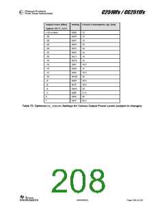
14.15 Output Power Programming
The RF output power level from the device is
programmed through the PA_TABLE0register.
Table 72 contains recommended PA_TABLE0
settings for various output levels and
frequency bands, together with current
consumption in the RF transceiver.
SWRS055D
Page 207 of 243

 TAOS [ TEXAS ADVANCED OPTOELECTRONIC SOLUTIONS ]