C2510Fx / CC2511Fx
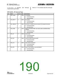
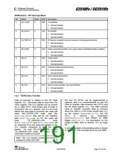
RFIM (0x91) – RF Interrupt Mask
Bit
Name
Reset
R/W
Description
7
IM_TXUNF
0
R/W
TX underflow
0
1
Interrupt disabled
Interrupt enabled
6
5
4
3
2
1
0
IM_RXOVF
IM_TIMEOUT
IM_DONE
IM_CS
0
0
0
0
0
0
0
R/W
R/W
R/W
R/W
R/W
R/W
R/W
RX overflow
0
1
Interrupt disabled
Interrupt enabled
RX timeout, no packet has been received in the programmed period.
0
1
Interrupt disabled
Interrupt enabled
Packet received/transmitted. Also used to detect underflow/overflow conditions
0
1
Interrupt disabled
Interrupt enabled
Carrier sense
0
1
Interrupt disabled
Interrupt enabled
IM_PQT
Preamble quality threshold reached.
0
1
Interrupt disabled
Interrupt enabled
IM_CCA
Clear Channel Assessment
0
1
Interrupt disabled
Interrupt enabled
IM_SFD
Start of Frame Delimiter, sync word detected
0
1
Interrupt disabled
Interrupt enabled
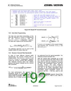
14.4 TX/RX Data Transfer
Data to transmit is written to the RF Data
register, RFD. Received data is read from the
same register. The RFDregister can be viewed
as a 1 byte FIFO. That means that if a byte is
received in the RFDregister, and it is not read
before the next byte is received, the radio will
enter RX_OVERFLOW state and the
RFIF.IRQ_RXOVF flag will be set together
with RFIF.IRQ_DONE. In TX, the radio will
RX and TX FIFOs can be implemented in
memory and it is recommended to use the
DMA to transfer data between the FIFOs and
the RF Data register, RFD. The DMA channel
used to transfer received data to memory
when the radio is in RX mode would have RFD
as the source (SRCADDR[15:0]), the RX
FIFO
in
memory
as
destination
(DRSTADDR[15:0]), and RADIO as DMA
trigger (TRIG[4:0]). For description on the
usage of DMA, refer to Section 13.5 on Page
99.
enter
TX_UNDERFLOW
state
(RFIF.IRQ_TXUVF and RFIF.IRQ_DONE will
be asserted) if too few bytes are written to the
RFD register compared to what the radio
expect. To exit RX_OVERFLOW and/or
TX_UNDERFLOW state, an SIDLE strobe
command should be issued.
A simple example of transmitting data is shown
in Figure 48. This example does not use DMA.
Note: The RFD register content will not be
retianed in PM2 and PM3
SWRS055D
Page 191 of 243

 TAOS [ TEXAS ADVANCED OPTOELECTRONIC SOLUTIONS ]